Handle for luggage

Inactive Publication Date: 2018-05-29
LAI WEI HUNG
View PDF16 Cites 5 Cited by
  • Summary
  • Abstract
  • Description
  • Claims
  • Application Information

AI Technical Summary

Benefits of technology

[0006]In view of the above, the primary objective of the present invention is to provide a handle for a luggage, which has a s

Problems solved by technology

A drawback the conventional handle is that it is free to rotate, so that the handle will move unexpectedly when a

Method used


Image

  • Handle for luggage
  • Handle for luggage
  • Handle for luggage

Examples


Example

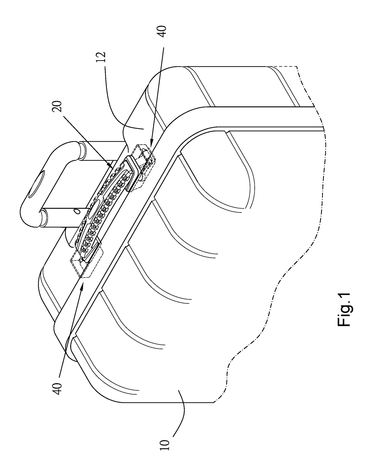
[0022]As shown in FIG. 1, a handle 20 of the first preferred embodiment of the present invention is mounted on a surface 12 of a case 10 through two connecting devices 40. The connecting devices 40 have the same structure, so we only describe one of them hereafter.

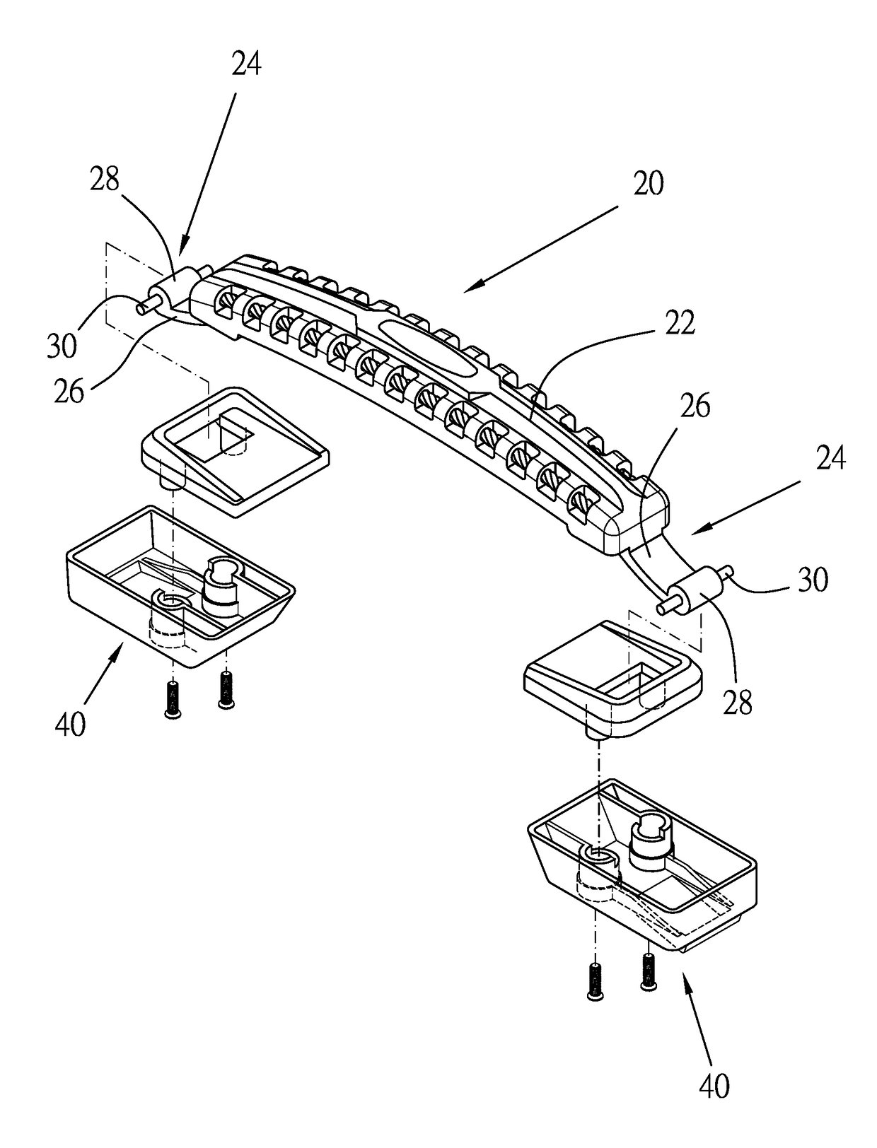
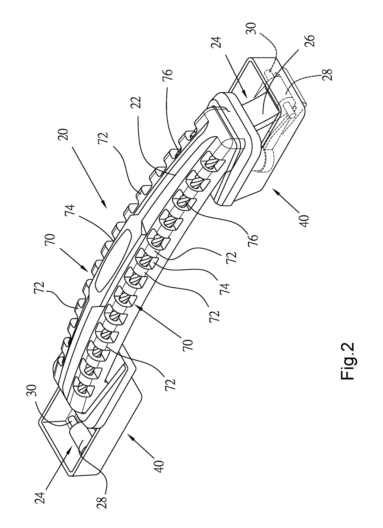
[0023]As shown in FIGS. 2 and 3, the handle 20 includes a main member 22 with two transmission assemblies 24 at opposite ends thereof. The transmission assemblies 24 are connected to the connecting devices 40 respectively. Each of the transmission assemblies 24 includes a connecting arm 26, a block 28 connected to the connecting arm 26, and a sliding rod 30. Opposite ends of the sliding rod 30 are projected from the block 28.

[0024]As shown in FIG. 4, each of the connecting devices 40 includes a base 42 and a pair of parallel rails 46 on a bottom 44 of the base 42. Each of the rails 46 has an inclined portion 48 at an end thereof The base 42 has a slot 50 on the bottom 44 between the rails 46 and two first tubes 52 projecte...


PUM


Abstract

A handle of a luggage includes a main member and two elastic members embedded in the main member. The main member has two hollow portions, each of which has a plurality of alternate spacers and recesses, and the elastic members pass through the spacers and the recesses and have opposite ends fixed to the main member. The main member is moved away from the surface of the case and the elastic members are deformed when a user holds the main member to lift the case, and the main member is moved to an initial position by the elastic members when the user releases the main member.

Description

BACKGROUND OF THE INVENTION[0001]1. Technical Field[0002]The present invention relates to a luggage, and more particularly to a handle for a luggage.[0003]2. Description of Related Art[0004]Typically, a conventional luggage is provided with a U-shaped handle pivoted on a case. The handle is leaned down on the case normally, and user has to grip it upwards to carry the luggage. A drawback the conventional handle is that it is free to rotate, so that the handle will move unexpectedly when a user move the luggage.[0005]An improved handle of a luggage is made of a flexible material. The improved handle will be attached to a case normally, and a user may grip it outwards to carry the luggage, and the handle will return automatically when the user does not grip it. Such handle is easy to be broken since the handle is moved relative to the case repeatedly.BRIEF SUMMARY OF THE INVENTION[0006]In view of the above, the primary objective of the present invention is to provide a handle for a lu...

Claims


Application Information

Patent Timeline
IPC IPC(8): A45C3/00A45C13/26
CPCA45C13/26
Inventor LAI, WEI-HUNG
Owner LAI WEI HUNG
Why Eureka
Try Eureka