Solar Cell Device Having Low Electrical and Thermal Impedance

Inactive Publication Date: 2010-11-11
INST NUCLEAR ENERGY RES ROCAEC
View PDF3 Cites 0 Cited by
  • Summary
  • Abstract
  • Description
  • Claims
  • Application Information

AI Technical Summary

Benefits of technology

[0004]The main purpose of the present invention is to adhere a light absorption region of a solar cell to a heat diss

Problems solved by technology

However, the above structure requires a complex procedure.
As a result, the fabricating time is prolonged and is not good for mass production.
In addition, the whole structure does not have enough heat dissipation efficiency.
He

Method used


Image

  • Solar Cell Device Having Low Electrical and Thermal Impedance
  • Solar Cell Device Having Low Electrical and Thermal Impedance
  • Solar Cell Device Having Low Electrical and Thermal Impedance

Examples


Example

[0010]The following description of the preferred embodiment is provided to understand the features and the structures of the present invention.

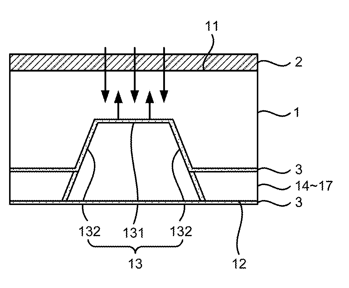
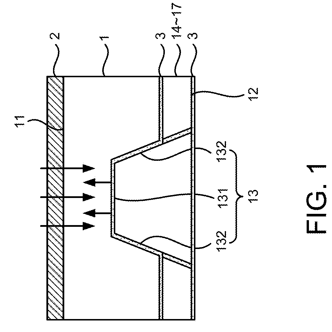
[0011]Please refer to FIG. 1, which is a sectional side view showing a preferred embodiment according to the present invention. As shown in the figure, the preferred embodiment is a solar cell device having low electrical and thermal impedance, comprising a substrate 1, a plurality of electric contact pads 2 and an ohmic contact 3.

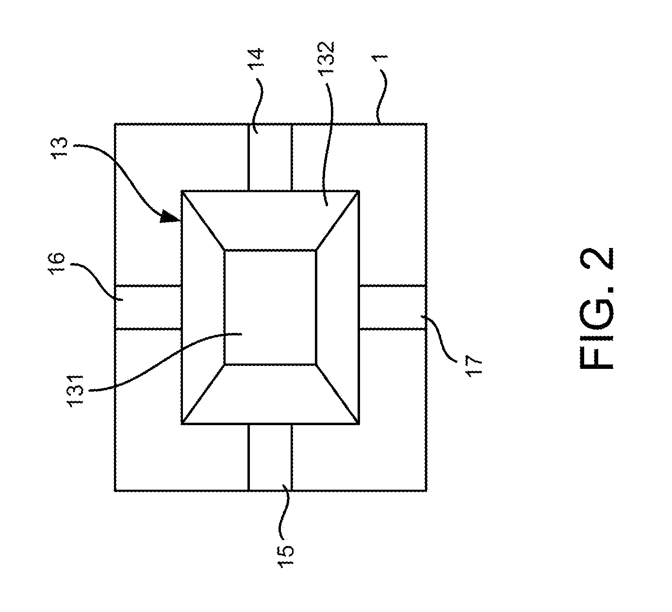
[0012]The substrate 1 has an upper surface 11 and a lower surface 12; the lower surface 12 is corresponding to the upper surface 11; the lower surface 12 has a columnar recessed hole 13 and four recessed channels 14˜17 connected with openings of the recessed hole 13; the recessed channel 13 is made of an electric and thermal conductive material; the recessed hole 13 comprises a central recess 131 and a recess sidewall 132 surrounding the central recess 131; and, every one of the recessed channels 14˜17 has a depth n...


PUM


Abstract

A solar cell is fabricated. Its light-absorbing part is close to a heat-diffusing device. Thus, the solar cell has low electrical and thermal Impedance. The solar cell has a strong structure, high efficiency and is fit for mass production.

Description

FIELD OF THE INVENTION[0001]The present invention relates to a solar cell device; more particularly, relates to adhering a light absorption region to a heat dissipation device for reducing an electric resistance and a thermal resistance with strong structure and high efficiency.DESCRIPTION OF THE RELATED ARTS[0002]A general solar cell device, as shown in FIG. 5, comprises a thin substrate 4 and a plurality of electric contact pads 5 deposed above the substrate 4, where the solar cell device can be adhered to a heat dissipation device 7 by using a bonding agent on a lower flat surface of the substrate 4.[0003]However, the above structure requires a complex procedure. For example, since the substrate 4 is weak during wire bonding on wafer, an extra substrate is needed for bonding; but the same extra substrate is removed later. As a result, the fabricating time is prolonged and is not good for mass production. In addition, the whole structure does not have enough heat dissipation effic...

Claims


Application Information

Patent Timeline
IPC IPC(8): H01L31/02
CPCH01L31/035281Y02E10/50H01L31/06H01L31/052
Inventor WU, CHIH-HUNG
Owner INST NUCLEAR ENERGY RES ROCAEC
Why Eureka
Try Eureka