Barrel apparatus for barrel plating

Inactive Publication Date: 2012-10-04
MITAKA SEISAKU
View PDF2 Cites 0 Cited by
  • Summary
  • Abstract
  • Description
  • Claims
  • Application Information

AI Technical Summary

Benefits of technology

[0027]The invention has the above-described configuration and function in which a non-open barrel is used so that, when the ratio of the diameter and the length is in the range of 1:0.7 to 1:1 even the long bolt class is capable of being plated without problems. A further advantage is that the electric resistance is capable of being decreased in the plating of a small workpiec

Problems solved by technology

However, the open type barrel has an opening section at an end surface of the barrel in the direction of the rotation shaft and the workpiece is accommodated in a portion that is defined by the diameter of the opening and an inner diameter of the barrel so that this is not appropriate because there is a problem that for example, long bolt or the like may be highly possible to run over from the opening.
In

Method used


Image

  • Barrel apparatus for barrel plating
  • Barrel apparatus for barrel plating
  • Barrel apparatus for barrel plating

Examples


Embodiment Construction

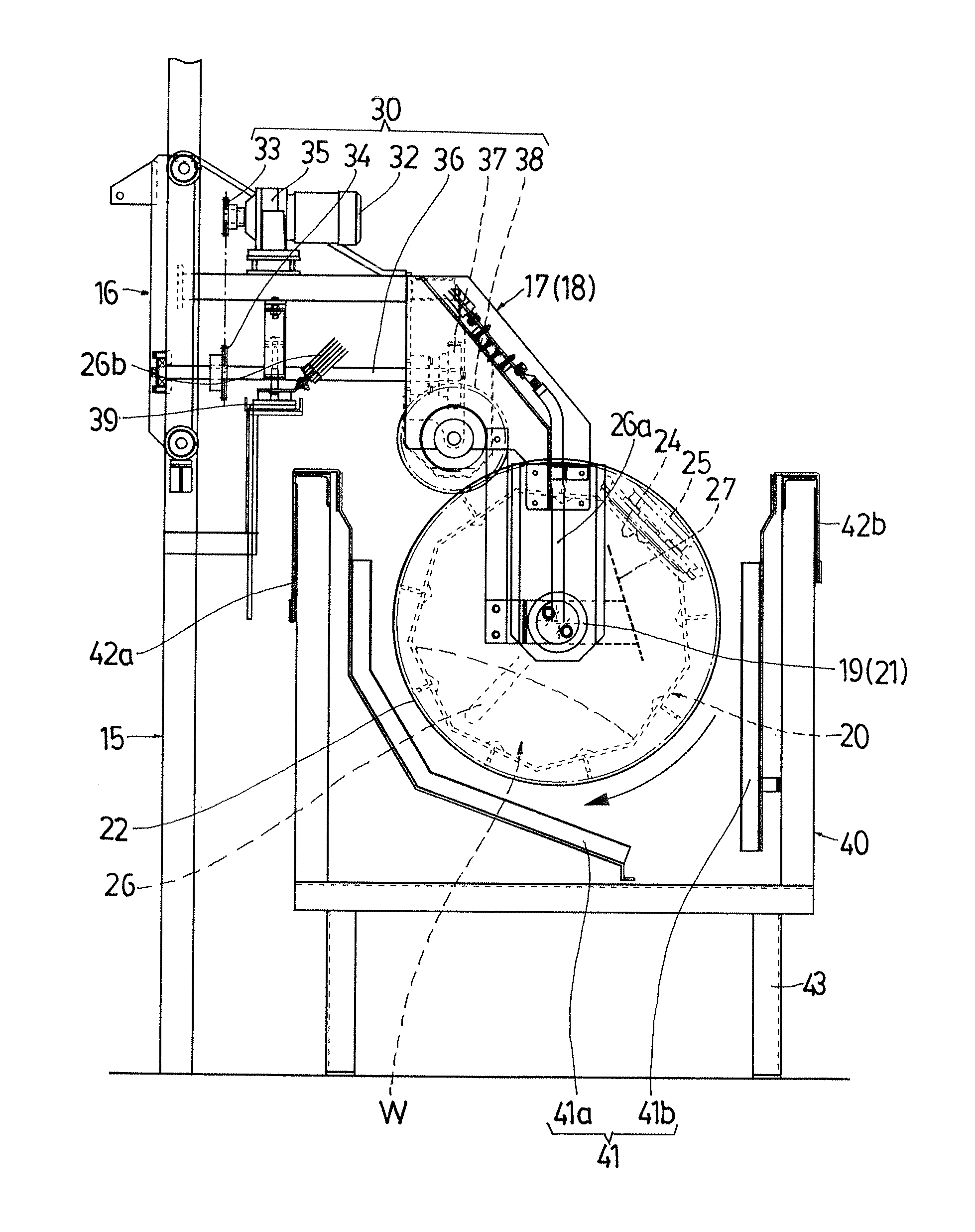
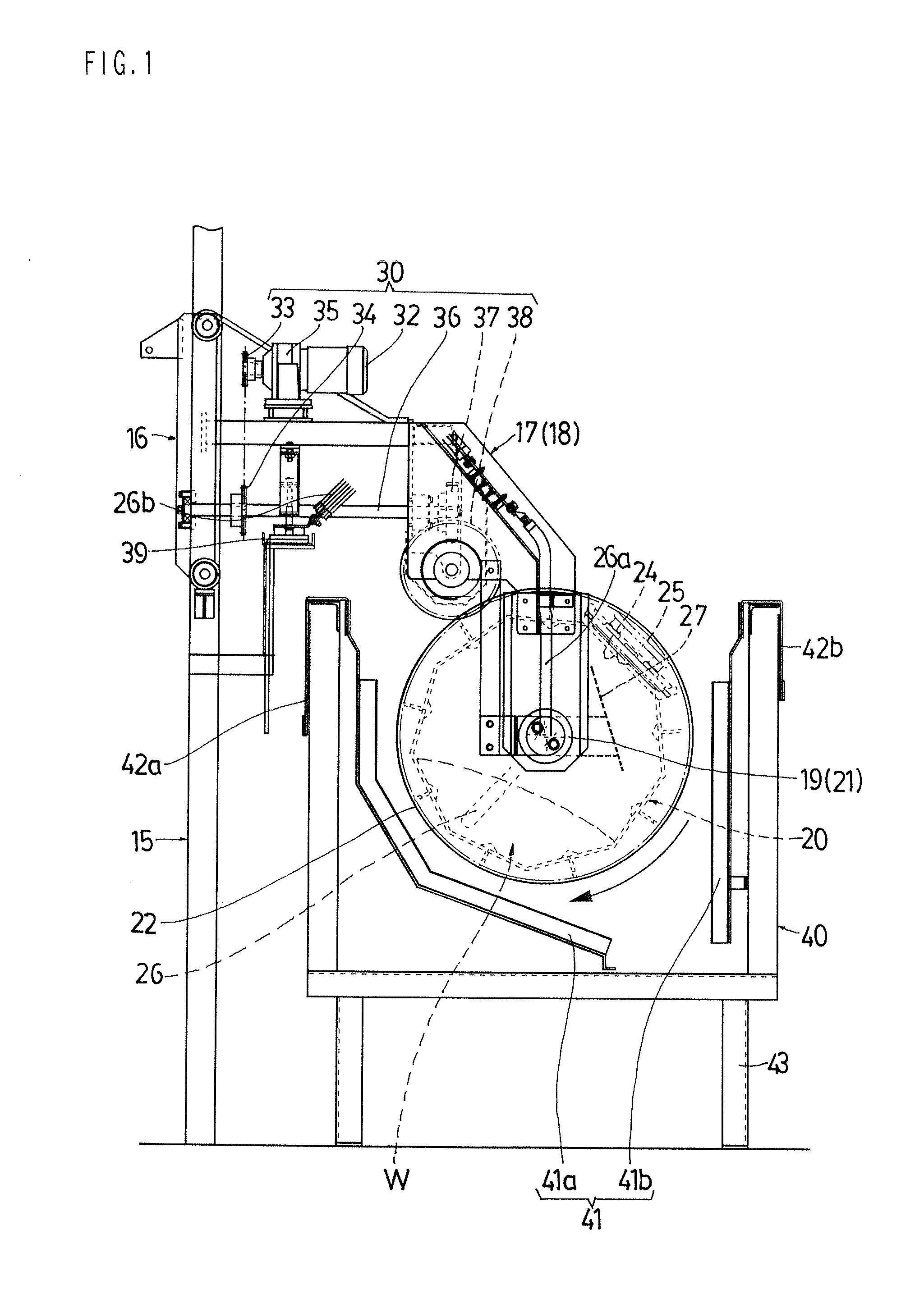
[0028]Hereinafter, embodiments of the invention will be described in detail with reference to the drawings. FIG. 1 is a front view illustrating a barrel apparatus for barrel plating of an embodiment according to the invention. In each of drawings, 15 is a supporting column of the barrel plating apparatus, 16 is an elevator. The elevator 16 is provided capable of being elevated using the supporting column 15 as a guide rail and arranged to travel in an elevator type line in a direction parallel to the paper surface in FIGS. 1. 17 and 18 are hanger arms that are configured of a pair of members in right and left, and attached to the elevator 16 at a base end section. Bearing sections 19 and 21 for a rotation shaft of the barrel are provided at the front end section thereof respectively. A barrel main body 20 of the barrel apparatus according to the invention is attached to portions of the bearing sections 19 and 21 of both front and rear end sections in a suspension-supporting state.

[0...


PUM


Abstract

A barrel apparatus for barrel plating in which a non-open type barrel is used, a workpiece is accommodated in the barrel and is immersed in a plating liquid, a negative electrode that is arranged within the barrel and a positive electrode that is arranged in the plating liquid are electrically connected and electroplating is performed while the barrel is rotated about a center shaft, includes a negative electrode arranged at a position that is in contact with a workpiece W inside the barrel, and a positive electrode is arranged at a position that is not in contact with the workpiece inside the barrel, wherein the barrel has a form that is substantially a cylinder or substantially a polygonal cylinder and a ratio between the diameter and the length thereof is in a range of 1:0.7 to 1:1.

Description

TECHNICAL FIELD[0001]The invention relates to a barrel apparatus for barrel plating in which a non-open barrel is used, a workpiece is accommodated inside the barrel and immersed in a plating liquid, a negative electrode that is arranged inside the barrel and a positive electrode that is arranged in the plating liquid are electrically connected and electroplating is performed while the barrel is rotated about a center shaft, and is specifically effective as measures for the environmental protection.BACKGROUND ART[0002]In a plating apparatus for industry, constant voltage control in which power supply is supplied to a plurality of barrels from one rectifier is performed. FIG. 5 shows a typical example of the above-described type of power supply. If the workpiece that is input into each barrel is different, the input amount is calculated beforehand and input so that a surface area of the workpiece is the same for each barrel. However, as shown in FIG. 5, if the lengths of the wires fr...

Claims


Application Information

Patent Timeline
IPC IPC(8): C25D17/00
CPCC25D17/20C25D17/12C25D17/007
Inventor SUZUKI, MICHIMASA
Owner MITAKA SEISAKU
Why Eureka
Try Eureka