Valve characteristic control apparatus for internal combustion engine

a valve characteristic and control apparatus technology, applied in the direction of electrical control, process and machine control, etc., can solve the problems of excessively rich air fuel ratio in the vicinity of the spark plug, deterioration of the combustion condition of the air fuel mixture, and inability of the catalyst to provide adequate purification performance, etc., to achieve the effect of reducing the hc discharge amount, reducing the combustible amount, and reducing the unfavorable air fuel mixtur

Active Publication Date: 2008-10-02
TOYOTA JIDOSHA KK
View PDF2 Cites 2 Cited by
  • Summary
  • Abstract
  • Description
  • Claims
  • Application Information

AI Technical Summary

Benefits of technology

[0017]When the retard amount of the closing timing of the exhaust valve is set larger, the amount of unburned HC intaken again to the combustion chamber is increased. At the same time, the internal EGR amount increases, which causes the combustion condition of the air fuel mixture to have a tendency to become more unstable. On the other hand, when the retard amount of the closing timing of the exhaust valve is set smaller, the amount of unburned HC intaken again to the combustion chamber reduces. However, since internal EGR amount reduces, a favorable air fuel mixture is formed that combusts more easily.
[0018]Note that, the combustion of the air fuel mixture has a tendency to become more unstable when the coolant temperature is low during the engine warming up operation. Accordingly, at such times, the retard amount may be set larger along with increase in the coolant temperature, thus enabling both (i) the combustion condition of the air fuel mixture to be made stable when the temperature is low, and (ii) the HC discharge amount to be reduced.
[0019]On the other hand, when the coolant temperature is somewhat high during the warming up operation, the HC discharge amount reduces because the catalyst is activated, and the temperature of the combustion gas is high. Accordingly, at such times, even if the retard amount is set smaller along with increase in the coolant temperature, the HC discharge amount can be adequately reduced, and a favorable air fuel mixture can be formed that is combusted more easily.
[0020]As will be understood from the above description, the optimal value for the retard amount of the closing timing of the exhaust valve has a close relationship to the coolant temperature. Accordingly, the retard amount of the closing timing of the exhaust valve can be set in accordance with the engine coolant temperature in order to appropriately set the retard amount of the exhaust valve closing timing in accordance with the engine coolant temperature and the number of injections of fuel. Further, by doing so, the HC discharge amount can be favorably reduced, and a favorable air fuel mixture can be formed that is combusted more easily.

Problems solved by technology

However, when a temperature of the catalyst is low when the engine is warming up, or the like, the catalyst is not able to provide adequate purification performance.
However, in an internal combustion engine in which catalyst warming up control is performed in the manner described above, if a fuel injection amount injected in the latter half of the compression stroke increases excessively, the air fuel ratio in the vicinity of the spark plug becomes excessively rich, which causes the combustion condition of the air fuel mixture to deteriorate.
However, if any one of the fuel injection amounts injected in the separated injections is less than a minimum injection amount of a fuel injection value (the minimum amount to which the fuel injection amount can be controlled), the separated injections cannot be performed.

Method used


Image

  • Valve characteristic control apparatus for internal combustion engine
  • Valve characteristic control apparatus for internal combustion engine
  • Valve characteristic control apparatus for internal combustion engine

Examples


Embodiment Construction

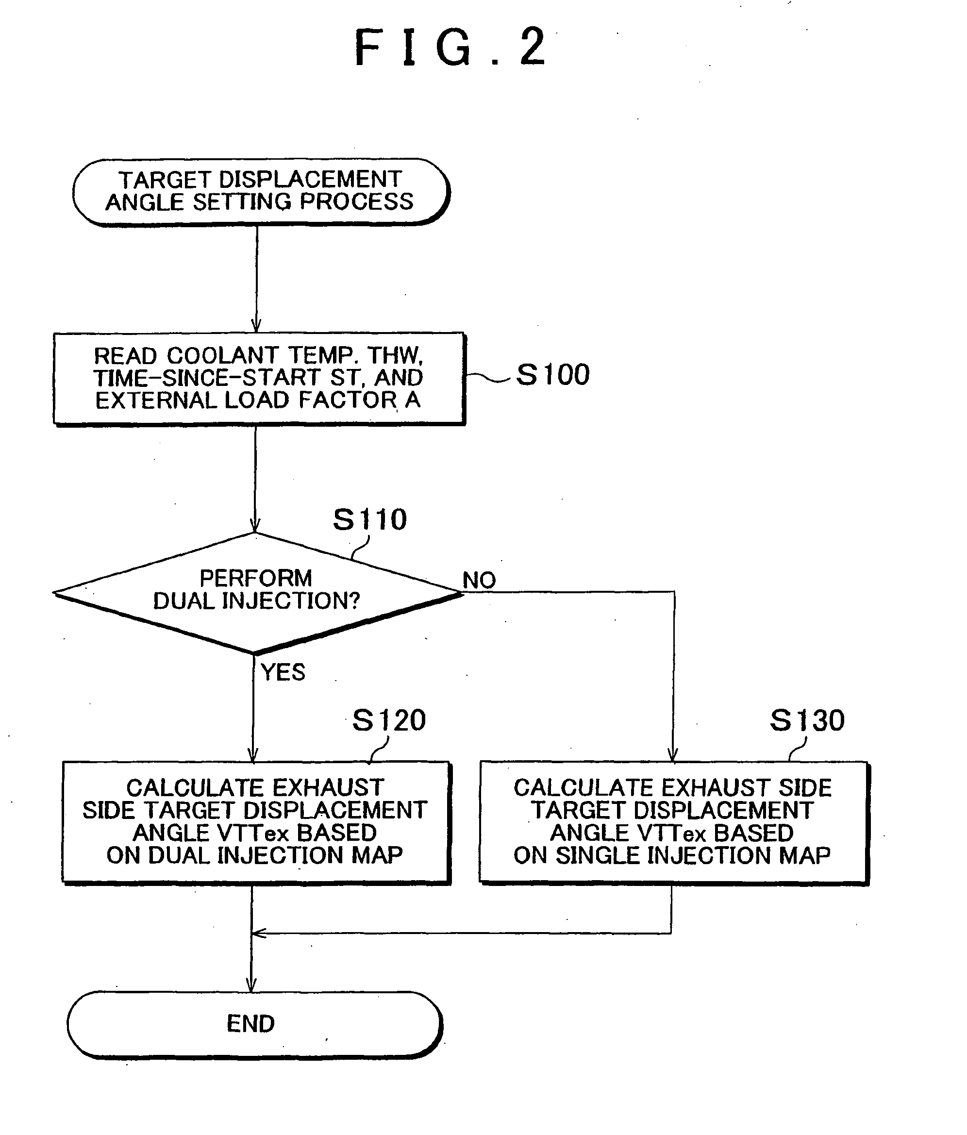
[0033]Hereinafter, an exemplary embodiment of a valve characteristic control apparatus for an internal combustion engine according to the invention will be described with reference to FIGS. 1 to 4.

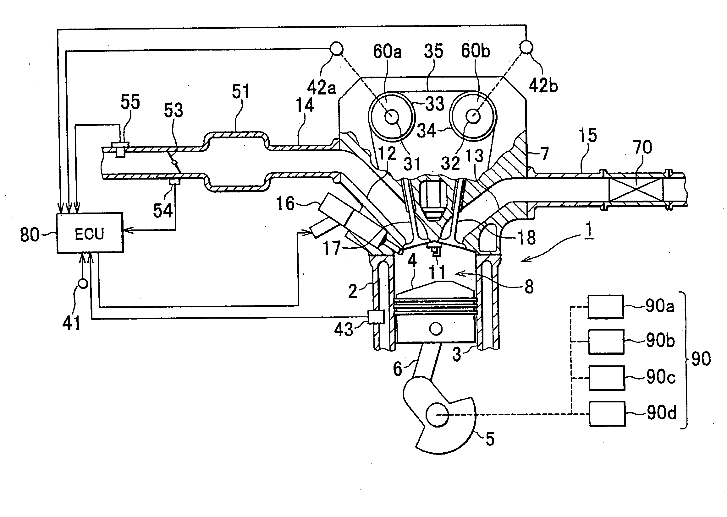
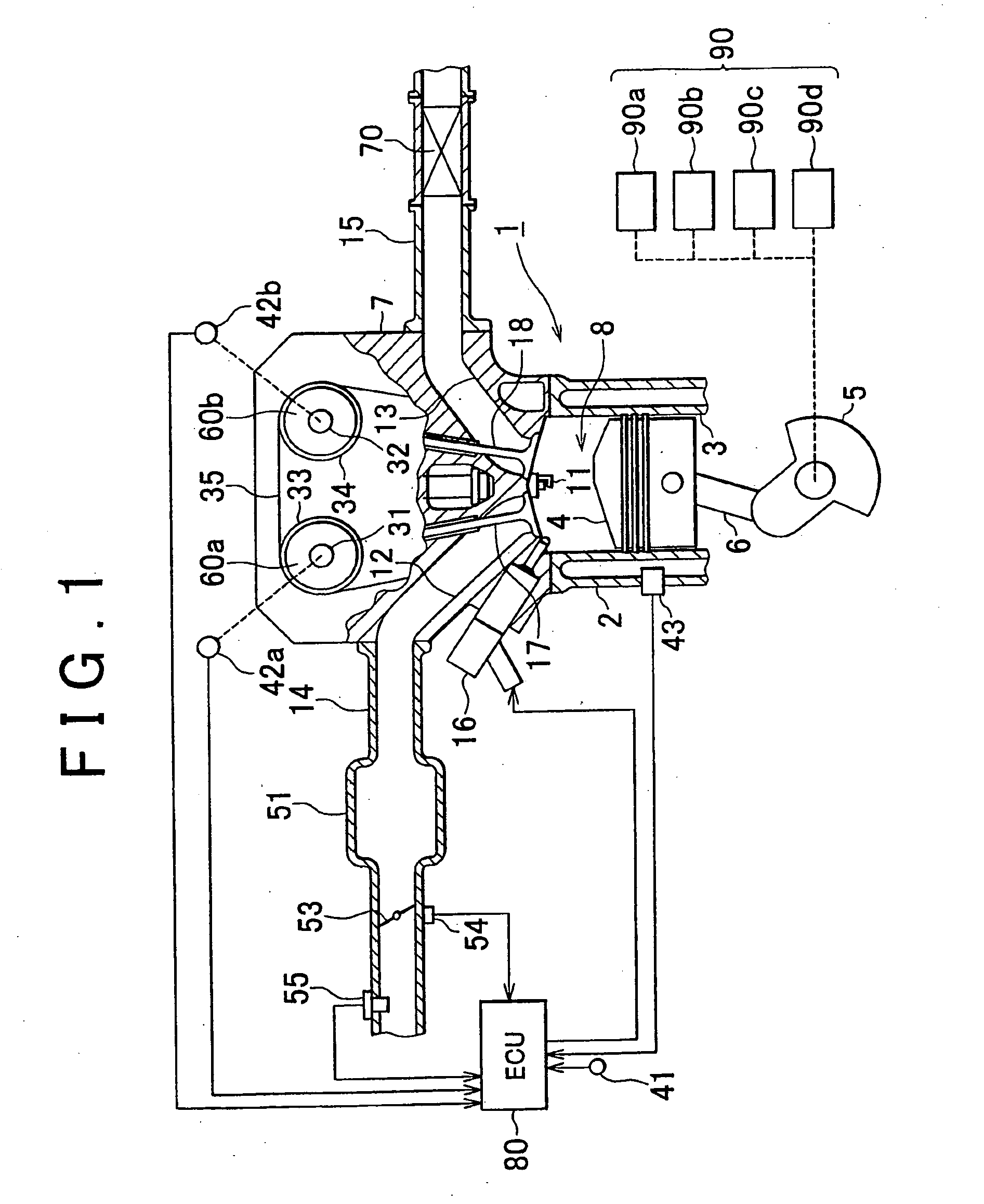
[0034]FIG. 1 shows a schematic diagram of a configuration of a gasoline engine 1 to which the valve characteristic control apparatus for the internal combustion engine according to the embodiment is applied.

[0035]A cylinder block 2 of the gasoline engine 1 is provided with a plurality of cylinders 3. (Only one of the cylinders 3 is shown in FIG. 1. For the sake of simplicity the following explanation will focus on this cylinder 3, although the same description applies to the other cylinders 3). A piston 4 is provided in the cylinder 3 and is linked to a crank shaft 5 via a control rod 6. The control rod 6 converts reciprocal movement of the piston 4 to rotational movement of the crank shaft 5. A coolant temperature sensor 43 for detecting an engine coolant temperature (coolant temperature ...


PUM


Abstract

A valve characteristic control apparatus is provided in an internal combustion engine including a variable valve mechanism that can change at the least, among valve characteristics of an exhaust valve, a closing timing of the exhaust valve, and in which a number of injections of fuel is changed during one engine cycle. The valve characteristic control apparatus sets the closing timing of the exhaust valve to a retard side during an engine warming up operation. When setting to the retard side is performed, if two injections are performed, an exhaust side target displacement angle VTTex of the exhaust valve is calculated based on a dual injection use map. On the other hand, if one injection is performed, the exhaust side target displacement angle VTTex of the exhaust valve is calculated based on a single injection use map.

Description

BACKGROUND OF THE INVENTION[0001]1. Field of the Invention[0002]The invention relates to a valve characteristic control apparatus for an internal combustion engine.[0003]2. Description of the Related Art[0004]In an internal combustion engine, exhaust gas components are purified by a catalyst. However, when a temperature of the catalyst is low when the engine is warming up, or the like, the catalyst is not able to provide adequate purification performance. To address this difficulty, various types of catalyst warming up control are performed in order to rapidly increase the temperature of the catalyst.[0005]For example, in an in-cylinder injection internal combustion engine that can directly inject and supply fuel to the combustion chamber, it is possible to increase a temperature of a combustion gas by, for example, (i) retarding an ignition timing, (ii) increasing an intake air amount to make an air fuel ratio leaner, and (iii) performing fuel injection in the latter half of the co...

Claims


Application Information

Patent Timeline
Patent Type & Authority Applications(United States)
IPC IPC(8): F02D41/00
CPCF02B23/104F02D13/0219F02D13/0261F02D41/0002F02D41/006F02D41/008F02D41/06F02D41/402F02D2013/0292F02D2041/001F02D2200/023F02M25/0752Y02T10/44Y02T10/42Y02T10/47Y02T10/18F02M26/01Y02T10/12Y02T10/40
Inventor IDOGAWA, MASANAOHOSOKAWA, OSAMU
Owner TOYOTA JIDOSHA KK
Why Eureka
Try Eureka