Droplet discharge head and pattern forming device

a discharge head and pattern forming technology, applied in printing, inks, printing, etc., can solve the problems of increasing viscosity, pattern formation cannot be high-quality, structure cannot achieve sufficient cooling effect with peltier elements, etc., to achieve simple structure, reduce platen gap, and reduce discharge amount

Inactive Publication Date: 2009-07-23
SEIKO EPSON CORP
View PDF13 Cites 2 Cited by
  • Summary
  • Abstract
  • Description
  • Claims
  • Application Information

AI Technical Summary

Benefits of technology

[0010]An advantage of the invention is to provide a droplet discharge head and a pattern forming device both in which the droplet discharge head is efficiently cooled.
[0011]According to a first aspect of the invention, a droplet discharge head includes: a droplet discharge head; and a nozzle plate that has a nozzle and is provided to the droplet discharge head. In the head, the nozzle plate is made of a peltier element. The droplet discharge head sequentially discharges a droplet of a functional liquid containing a functional material from the nozzle to a substrate so as to form a pattern on a surface of the substrate.
[0012]The droplet discharge head can block off heat transmitted through the nozzle plate, preventing the functional liquid from being heated by outside heat. As a result, the fluctuation of the discharge amount can be lowered without being influenced by outside temperature. Employing the nozzle plate made of the peltier element allows simplifying the structure as well as reducing the platen gap.
[0013]In the head, the nozzle plate made of the peltier element may include a cooling portion and a heat generating portion and be provided to the droplet discharge head so that the cooling portion faces a side adjacent to the droplet discharge head while the heat generating portion faces a side adjacent to the substrate.
[0014]The droplet discharge head can cool the functional liquid supplied to the droplet discharge head as well as heat the substrate.
[0015]In the droplet discharge device, the substrate may be a low-temperature firing sheet including ceramic particles and resin, and the functional liquid may be a metal ink in which metal particles are dispersed as the functional material.

Problems solved by technology

The heat causes the following problems: the functional liquid discharged from the droplet discharge head is heated, resulting in increasing the viscosity; nozzle pitches vary due to the thermal expansion of a nozzle plate; and a discharge amount varies due to a drying of a solution stuck inside the droplet discharge head.
As a result, patterns cannot be formed with high accuracy.
Thus, this structure does not achieve sufficient cooling effect with the peltier element because heat from the heated substrates transmits to the droplet discharge head through the nozzle plate facing the substrate.
The above-described problems still remain, such as a decreasing of the viscosity of the functional liquid.

Method used


Image

  • Droplet discharge head and pattern forming device
  • Droplet discharge head and pattern forming device
  • Droplet discharge head and pattern forming device

Examples


Embodiment Construction

[0029]An embodiment of the invention will be described with reference to FIGS. 1 to 5. In a circuit module in which a semiconductor chip is built in a low temperature co-fired ceramic (LTCC) multilayer substrate, the invention is embodied in forming wiring patterns drawn on a plurality of low-temperature firing sheets (green sheets) included in the LTCC multilayer substrate.

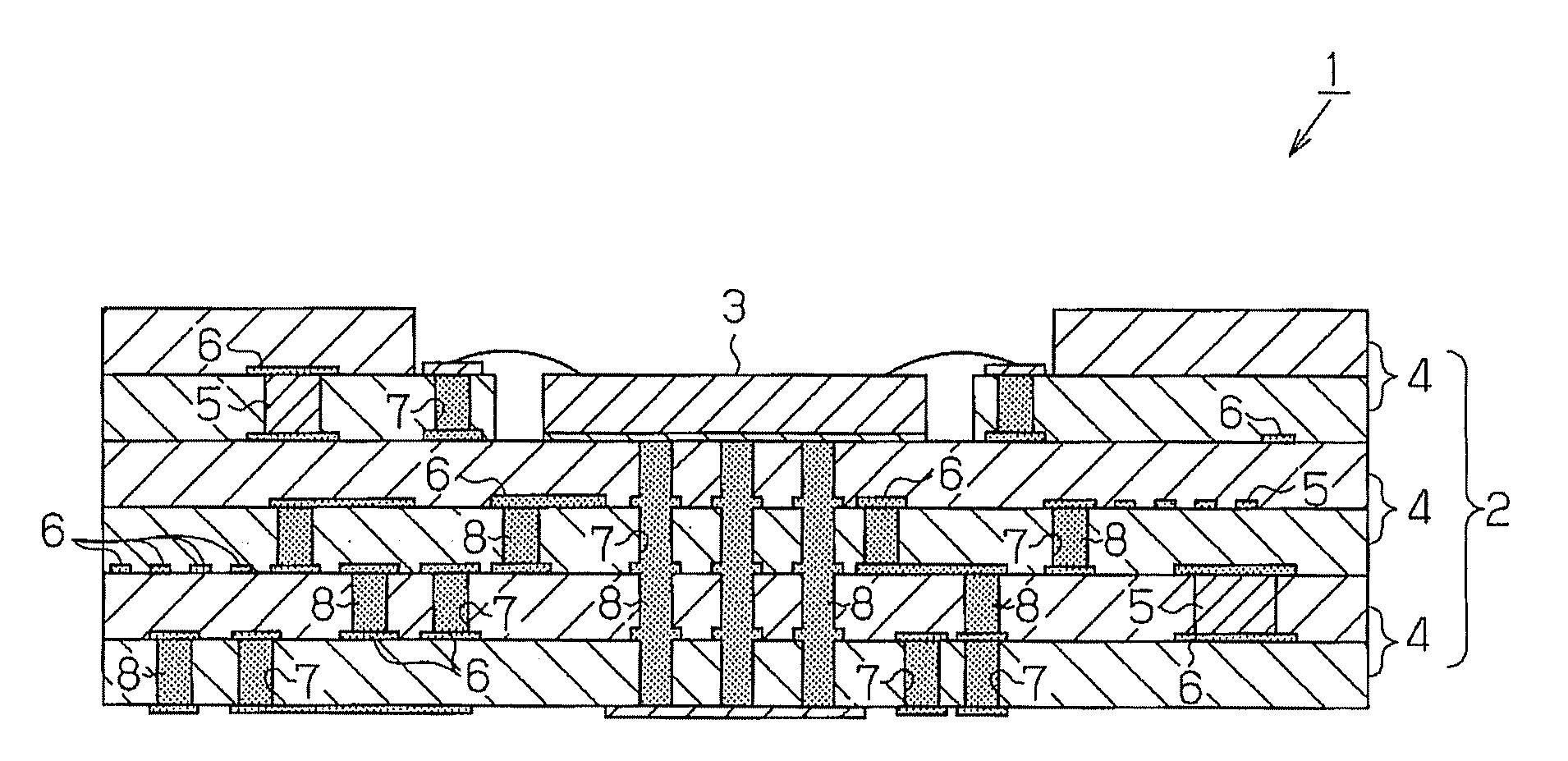
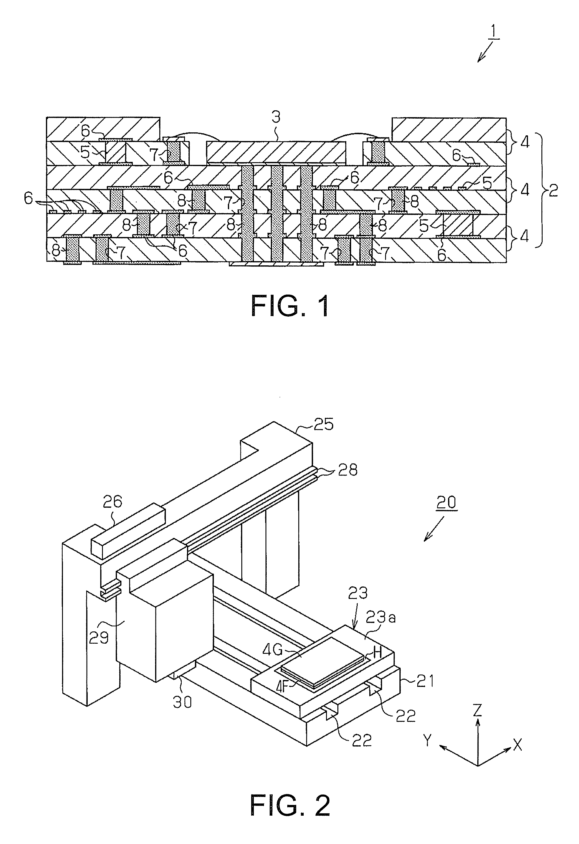
[0030]First, the circuit module is described in which the semiconductor chip is mounted on the LTCC multilayer substrate. FIG. 1 is a sectional view of a circuit module 1. The circuit module 1 includes an LTCC multilayer substrate 2 and a semiconductor chip 3. The LTCC multilayer substrate 2 is formed into a board shape. The semiconductor chip 3 is connected to an upper side of the LTCC multilayer substrate 2 by wire bonding.

[0031]The LTCC multilayer substrate 2 is a laminated body of a plurality of low-temperature fired substrates 4 each of which is formed into a sheet shape. Each low-temperature fired substrate...


PUM


Abstract

A droplet discharge head includes: a droplet discharge head; and a nozzle plate that has a nozzle and is provided to the droplet discharge head. The nozzle plate is made of a peltier element. A droplet of a functional liquid containing a functional material is sequentially discharged from the nozzle to a substrate so as to form a pattern on a surface of the substrate.

Description

BACKGROUND[0001]1. Technical Field[0002]The present invention relates to a droplet discharge head and a pattern forming device.[0003]2. Related Art[0004]Conventionally, there has been known a method for forming a linear pattern on a substrate by using a droplet discharge device. In the method, the droplet discharge device discharges droplets of a functional liquid. For example, refer to JP-A-2005-34835.[0005]Generally, the droplet discharge device includes a substrate placed on a stage, a droplet discharge head discharging droplets of a functional liquid containing a functional material to the substrate, and a mechanism moving the substrate (stage) and the droplet discharge head relatively and two-dimensionally. The device disposes the droplets discharged from the droplet discharge head at any position on a surface of the substrate. In this case, each of the droplets discharged on the surface of the substrate is sequentially disposed in such a manner that the spreading range of each...

Claims


Application Information

Patent Timeline
Patent Type & Authority Applications(United States)
IPC IPC(8): B41J2/14B41J29/38
CPCB05B17/0607B41J2/1408B41J2/14274H05K3/1241B41J2202/08C09D11/30C09D11/52B41J2/1433
Inventor IWATA, YUJI
Owner SEIKO EPSON CORP
Why Eureka
Try Eureka