Multipath interconnect with meandering contact cantilevers

Inactive Publication Date: 2005-05-05
K & S INTERCONNECT +2
View PDF17 Cites 0 Cited by
  • Summary
  • Abstract
  • Description
  • Claims
  • Application Information

AI Technical Summary

Benefits of technology

[0007] An interconnect assembly includes a number of interconnect stages combined in a preferably planar carrier structure. Each interconnect stage includes at least two contact sets having an upwards pointing cantilever contact and a downwards pointing cantilever contact. The cantilever contacts are attached with a common base onto framing elements of the carrier structure. The framing elements are arranged around openings in the carrier structure such that the downward pointing cantilever contacts may reach through the carrier structure. Each contact set defines an independent conductive path between a sin

Problems solved by technology

Also commonly affected by fatigue failure is the connecting interface of the conductive structure with the non condu

Method used


Image

  • Multipath interconnect with meandering contact cantilevers
  • Multipath interconnect with meandering contact cantilevers
  • Multipath interconnect with meandering contact cantilevers

Examples


Example

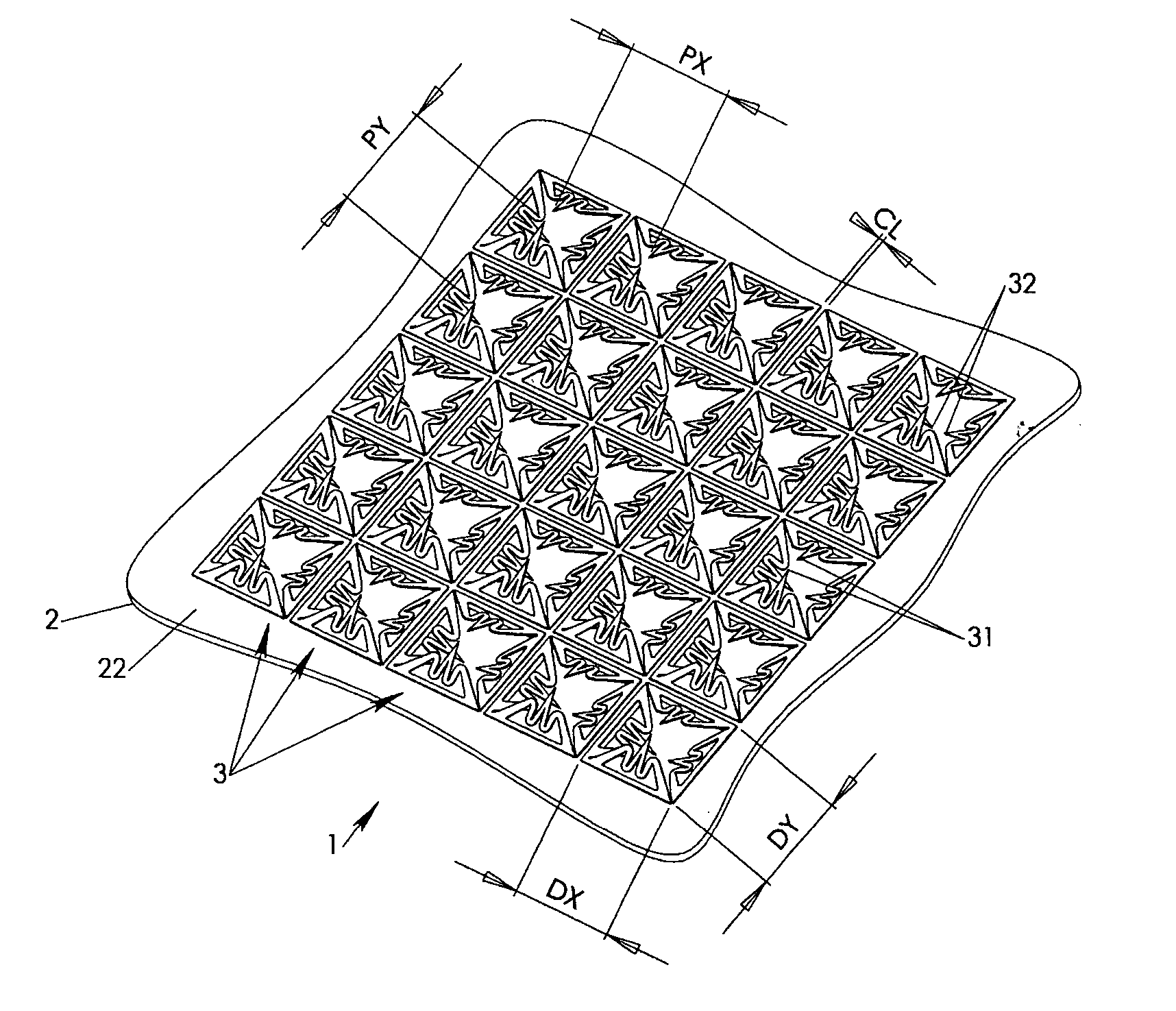
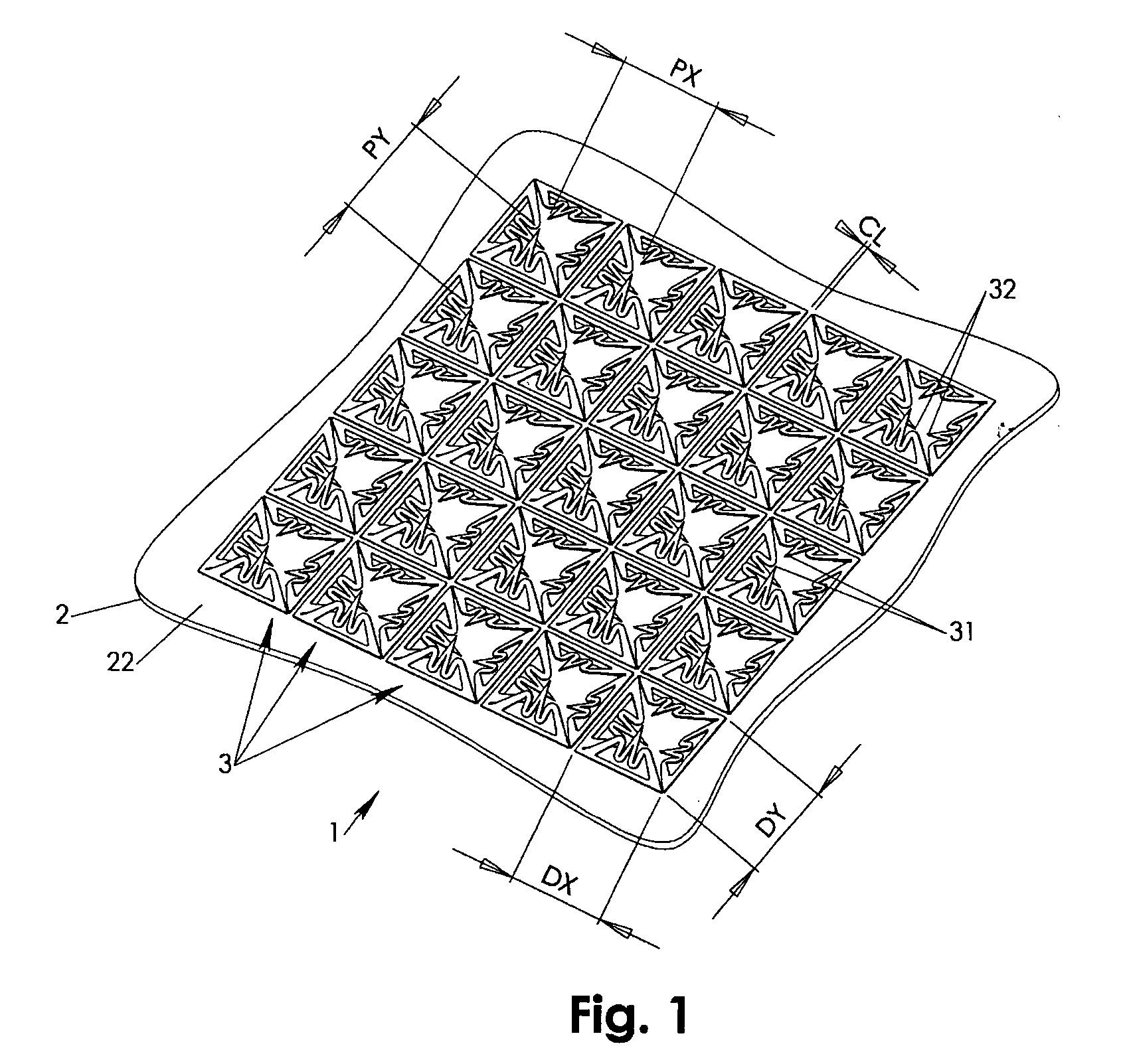
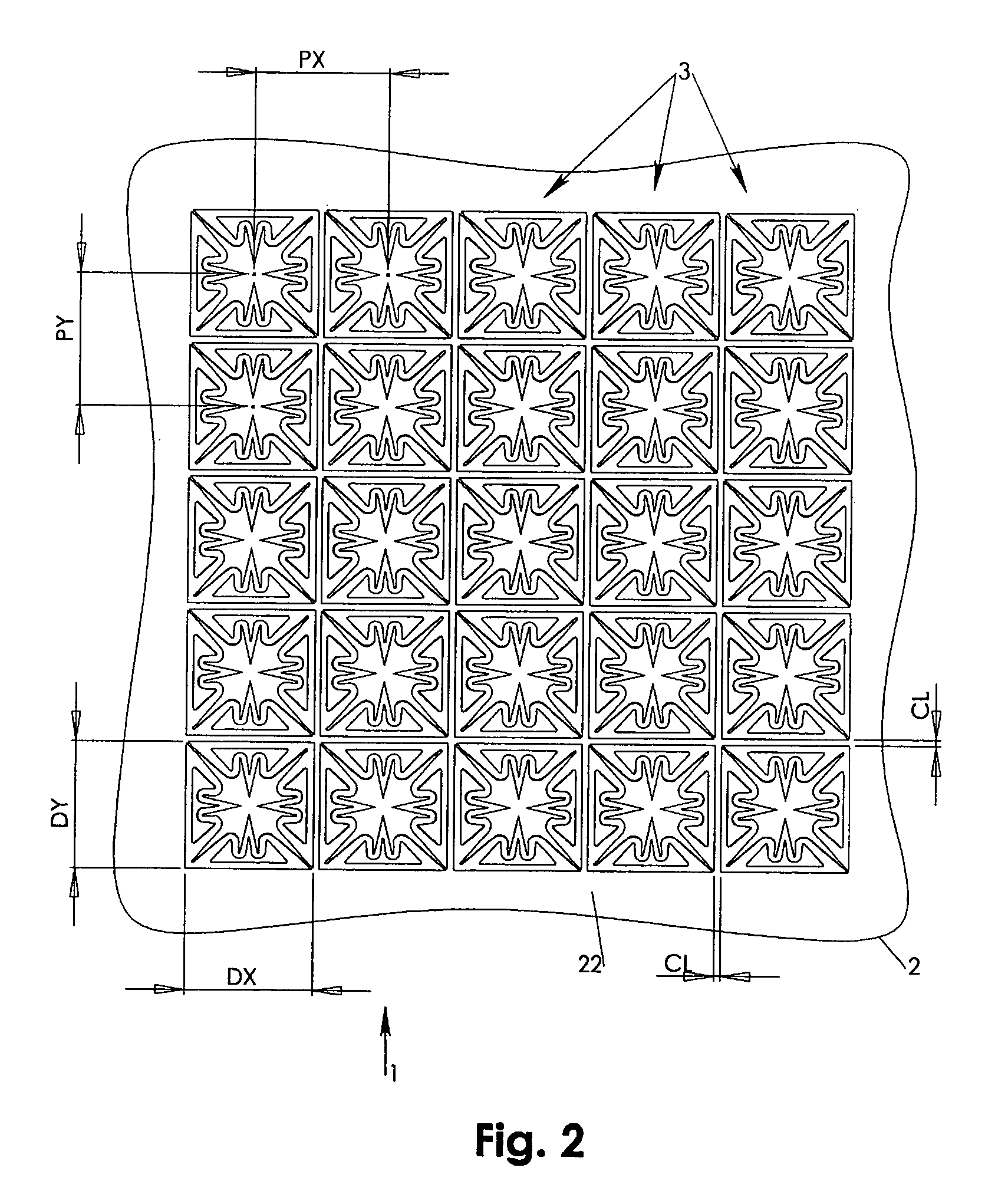
[0028] According to FIGS. 1-3, an interconnect assembly 1 may include a carrier structure 2 made of a rigid, non conductive material such as PCB. The carrier structure 2 holds a number of interconnect stages 3 that are two dimensionally arrayed with pitches PX and PY. The pitches PX, PY are defined in conjunction with pitches of a tested circuit chip contacts as is well known in the art.

[0029] Preferably each but at least one of the interconnect stages 3 features at least two but preferably four upwards pointing meandering cantilever contacts 31 and at least two but preferably four downwards pointing meandering cantilever contacts 32. The interconnect stages 3 are attached at the top face 22 of the carrying structure 2. At this point it is noted that the terms “top, bottom, upwards, downwards” are introduced for the sole purpose of establishing relative directional relations between individual components rather than spatial position or orientations.

[0030] Preferably each but at le...


PUM


Abstract

An interconnect assembly includes a number of interconnect stages combined in a carrier structure. Each interconnect stage includes at least two contact sets having an upwards pointing cantilever contact and a downwards pointing cantilever contact. The cantilever contacts are attached to the carrier structure and are arranged around openings in the carrier structure such that the downward pointing cantilevers may reach through the carrier structure. Each contact set defines an independent conductive path between a single pair of opposing chip and test apparatus contacts such that multiple conductive paths are available for each interconnect stage for increased transmission reliability and reduced resistance. The cantilever contacts have a meandering contour and are either combined in symmetrical pairs at their respective tips or are free pivoting. The meandering contour provides a maximum deflectable cantilever length within an available footprint defined by the pitch of the tested chip.

Description

FIELD OF INVENTION [0001] The present invention relates to interconnect assemblies for repetitively establishing conductive contact between opposing contact arrays. Particularly, the present invention relates to interconnect assemblies having a number of arrayed interconnect stages including meandering cantilever contacts combined with a planar carrier structure. BACKGROUND OF INVENTION [0002] Demand for ever decreasing chip fabrication costs forces the industry to develop new solutions for inexpensive and reliable chip testing devices. A central component for repetitively contacting contact arrays of tested circuit chips is an interconnect assembly that is placed adjacent a test apparatus contact array that has contact pitch corresponding to the tested chips' carrier (package) contact pitch. During packaged chip testing, a package is brought with its contact array into contact with the interconnect assembly such that an independent conductive contact is established between each of ...

Claims


Application Information

Patent Timeline
IPC IPC(8): H01R12/04H01R12/71H01R13/24
CPCH01R13/2407H01R12/714H01R13/2485H01R13/2428H01R13/24
Inventor KISTER, JANUARYJAQUETTE, JAMESFAHRNER, STEVE
Owner K & S INTERCONNECT
Why Eureka
Try Eureka