
Miniaturized talbot spectrometer

Inactive Publication Date: 2002-09-12
THE BOARD OF TRUSTEES OF THE LELAND STANFORD JUNIOR UNIV
View PDF0 Cites 27 Cited by
  • Summary
  • Abstract
  • Description
  • Claims
  • Application Information

AI Technical Summary

Benefits of technology

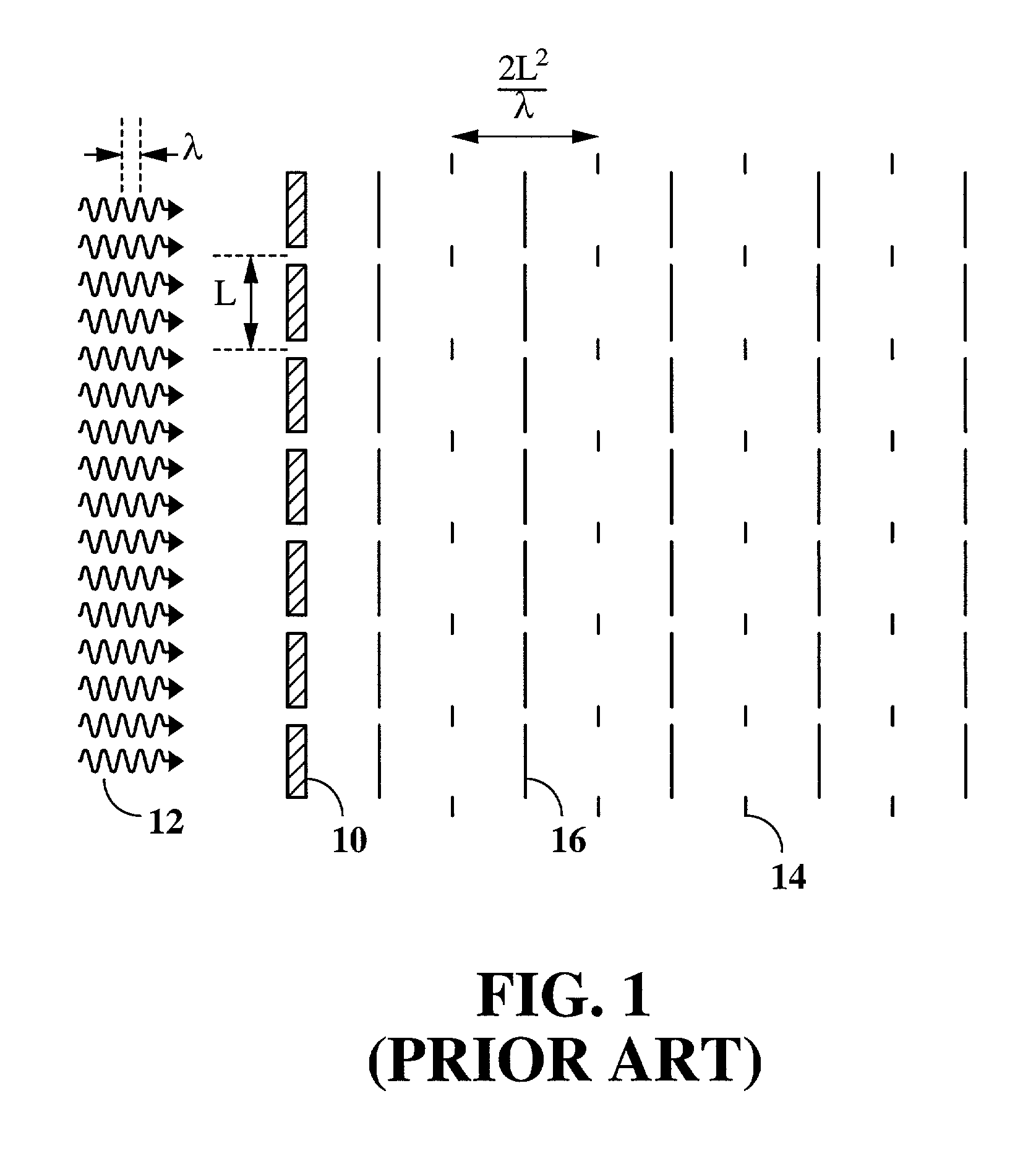
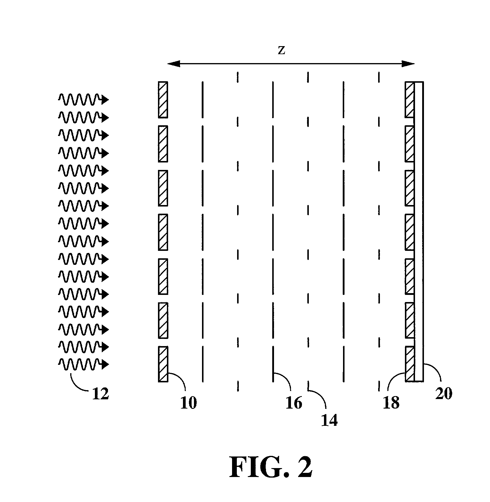
[0005] The present invention provides compact, inexpensive, nanometer-resolution spectrometers that are designed to sense, monitor, and process the spectral content of images. These spectrometers are ideally suited for hand-held spectral imaging and sensing systems. The advance of MEMS (Micro-Electro-Mechanical-Systems) technology has made possible various types of small spectrometers, including Fabry-Perot interferometers, grating-based spectrometers, and standing wave spectrometers. This invention, however, provides a novel type of miniaturized spectrometer based on the Talbot effect.
[0007] This novel class of transform spectrometers are simple, compact, low-cost, high precision, and versatile. These novel transform spectrometers are well suited for a variety of applications involving spectral imaging and sensing. Unlike typical transform spectrometers, embodiments of the present invention may be constructed without any moving parts, thus increasing reliability. The spectrometer also enjoys the multiplexing advantage of other types of transform spectrometers, i.e. the presence of all frequencies of light at the detector at all times provides an increased signal-to-noise ratio. As with other more common transform spectrometers, there is no free spectral range to limit the spectral sensing region. Only the detector response limits the range. Hence spectrometers of the present invention may be useful when a large wavelength range is needed in a compact device.

Problems solved by technology

Most existing spectrometers are bulky because of their use of gratings, prisms or large interferometers.
These spectrometers are not suitable for a variety of potential applications which require very compact spectrometers, e.g., spectrometer arrays.
A spectrometer built according to Lohmann's teaching, however, would not be sufficiently compact for many applications and would have moving parts that would decrease its reliability.

Method used


Image

  • Miniaturized talbot spectrometer
  • Miniaturized talbot spectrometer
  • Miniaturized talbot spectrometer

Examples


first embodiment

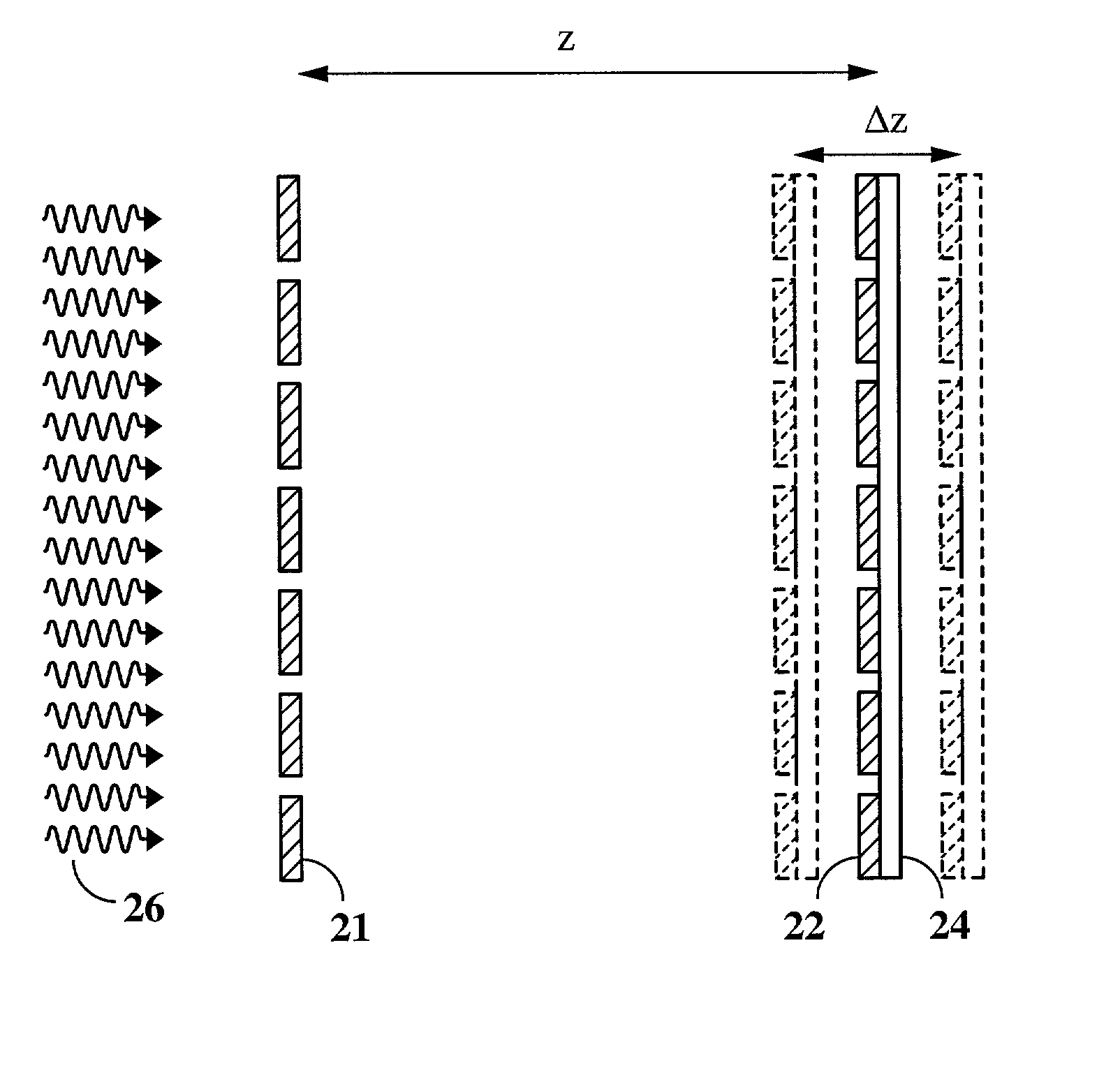
[0018] As illustrated in FIG. 3, the present invention comprises a first spatially periodic object 21 (e.g., a grating), a second spatially periodic object 22 having the same periodicity pattern as the first object 21, and a detector 24 positioned in contact with, or in very close proximity to the second spatially periodic object 22. In the present context, a spatially periodic object is defined as a planar or approximately planar object having spatial periodicity in one and / or two spatial dimensions of its plane (e.g., a grating with horizontal and / or vertical lines). For simplicity, the term "grating" will be used hereafter to refer to any such spatially periodic object, and its "pattern" will be used to refer to its particular pattern of spatial periodicity.

[0019] The two gratings 21 and 22 are oriented parallel to each other and positioned perpendicular to a common optical axis with their patterns rotationally aligned. The gratings are separated by a distance z along the optical...

second embodiment

[0023] the present invention, shown in FIG. 4, does not require mechanical movement of the components. In this embodiment, light 28 passes through a first grating 30 and generates Talbot images, just as before. A CCD or other type of detector array 34, however, is fixed at a small angle .theta., as shown. As a result, different parts of the detector detect Talbot images at different distances, covering a range of .DELTA.z. The same effect can be produced by fabricating the detector in the form of a "staircase." In either case, each row of pixels in the array measures the image intensity at a different distance in the z-direction. As a result, the various rows together provide a measure of the periodicity of the Talbot self-images. An advantage of this embodiment is that it does not involve any moving parts, and is able to measure the intensities at all the distances simultaneously. It should be noted that, instead of tilting the second detector, the first grating may be tiled instea...

third embodiment

[0025] In the present invention, shown in FIG. 5, a single structure is made both to generate and to detect Talbot self-images. The structure comprises a periodic array of detectors 36 grown on a transparent substrate 38. The device works by shining light 40 though the structure, reflecting the diffracted light off a mirror 42 and then detecting the reflected light with the detectors 36. The structure, for example, can be made of vertically grown PIN detectors. Other types of detectors, such as vertical stacks of PIN diodes or photoconductors (PIP or NIN) grown on a transparent substrate, can also be used. Each detector element has a thick doped region grown on the substrate, an intrinsic region grown on the thick doped region, and a thin doped region grown on the intrinsic region. Light 40 passes through the transparent substrate and either passes between the detectors or is absorbed in the thick doped (N or P) region of each detector and thus does not generate significant photocur...


PUM


Abstract

A transform spectrometer determines the spectrum of light based on the Talbot effect. Light to be analyzed is passed through a spatially periodic object, thereby generating a series of Talbot images. The intensities of these Talbot images at different optical distances from the spatially periodic object are then detected, and Fourier transformed to determine the spectrum of the light. Preferably, the detector comprises a spatial masking pattern such that the intensities detected are maximized at Talbot planes or at the midpoints between Talbot planes. In one embodiment, the optical distance between the spatially periodic object and the detector is changed in order to detect image intensities at different Talbot planes. In another embodiment, the detector and the spatially periodic object are positioned along a common optical axis at relative angle .theta. such that different detector rows detect intensities at different Talbot planes. In yet another embodiment, the spatially periodic object is both a grating and a detector, and the Talbot images generated by the grating are reflected off a mirror back to the detector.

Description

CROSS-REFERENCE TO RELATED APPLICATIONS[0001] This application claims priority from U.S. provisional application no. 60 / 247409 filed Sept. 10, 2000, which is incorporated herein by reference.FIELD OF THE INVENTION[0003] This invention relates generally to spectrometers and spectral sensors. More particularly, it relates to novel types of compact spectrometers based on the Talbot effect.BACKGROUND ART[0004] Most existing spectrometers are bulky because of their use of gratings, prisms or large interferometers. These spectrometers are not suitable for a variety of potential applications which require very compact spectrometers, e.g., spectrometer arrays. Compact spectrometer arrays would also benefit from spectrometers having a linear architecture, so that each pixel of an image may be analyzed by its own spectrometer. In order to be useful, such spectrometers would need to provide adequate resolution and be sufficiently inexpensive to manufacture. A technique for wavelength measureme...

Claims


Application Information

Patent Timeline
IPC IPC(8): G01J3/45
CPCG01J3/02G01J3/0229G01J3/0256G01J3/45G01J3/453
Inventor KUNG, HELEN L.MILLER, DAVID A.B.
Owner THE BOARD OF TRUSTEES OF THE LELAND STANFORD JUNIOR UNIV
Learn More