
LED tube lamp

a technology of led tubes and lamps, applied in the direction of lighting and heating apparatus, semiconductor devices for light sources, lighting support devices, etc., can solve the problem of heaviness of electric shock risk, and achieve the effect of reducing the risk of electric shock and discharging heat more efficiently

Active Publication Date: 2018-05-29
JIAXING SUPER LIGHTING ELECTRIC APPLIANCE
View PDF132 Cites 0 Cited by
  • Summary
  • Abstract
  • Description
  • Claims
  • Application Information

AI Technical Summary

Benefits of technology

The invention provides an LED tube lamp that is more efficient at dissipating heat, stronger in construction, and safer from electrical shocks.

Problems solved by technology

It is therefore one of the important issues to solve the heat dissipation problem of the LED products.
This design improves heat dissipation but heightens the risk of electric shocks.

Method used


Image

  • LED tube lamp
  • LED tube lamp
  • LED tube lamp

Examples


Embodiment Construction

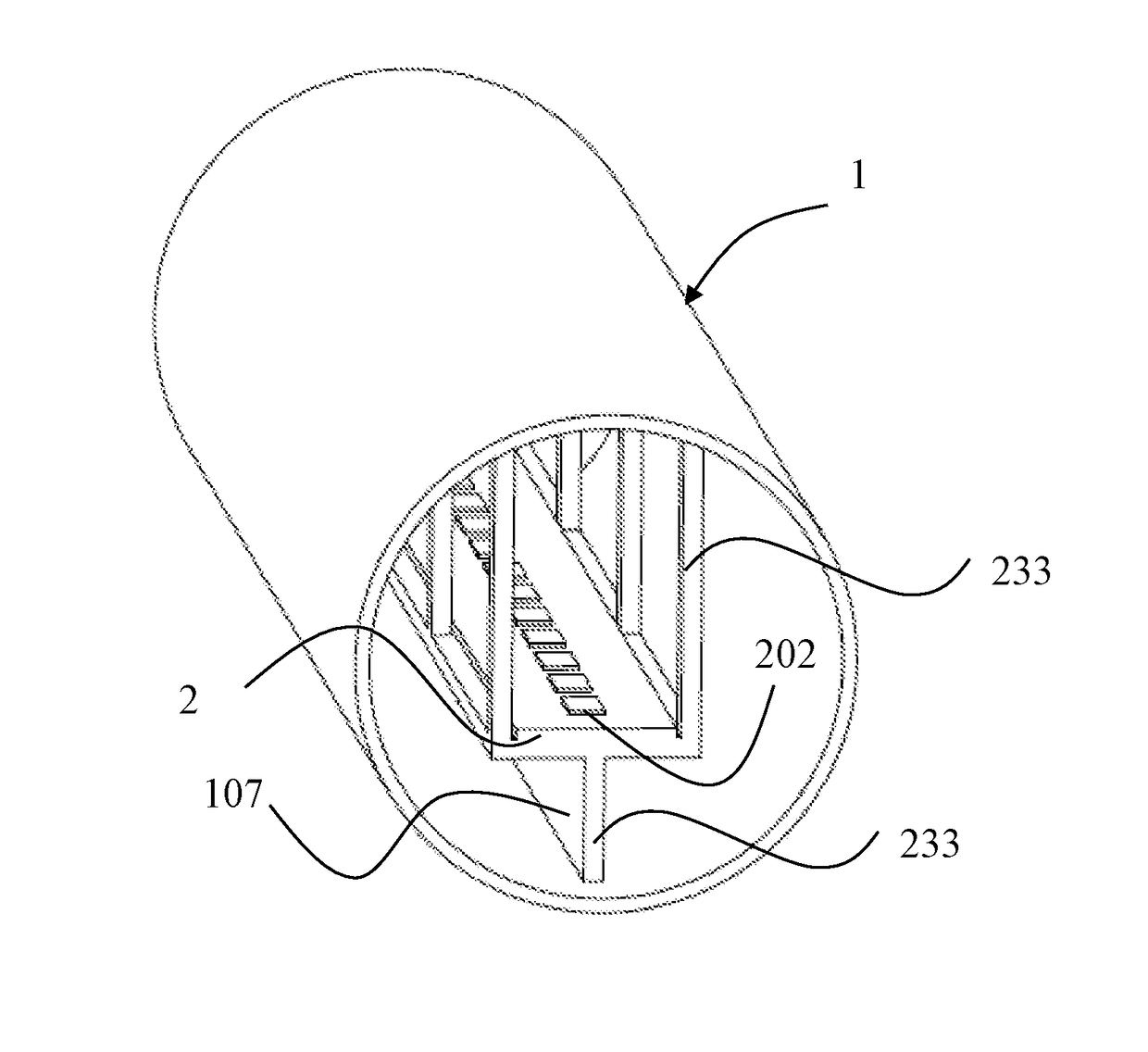
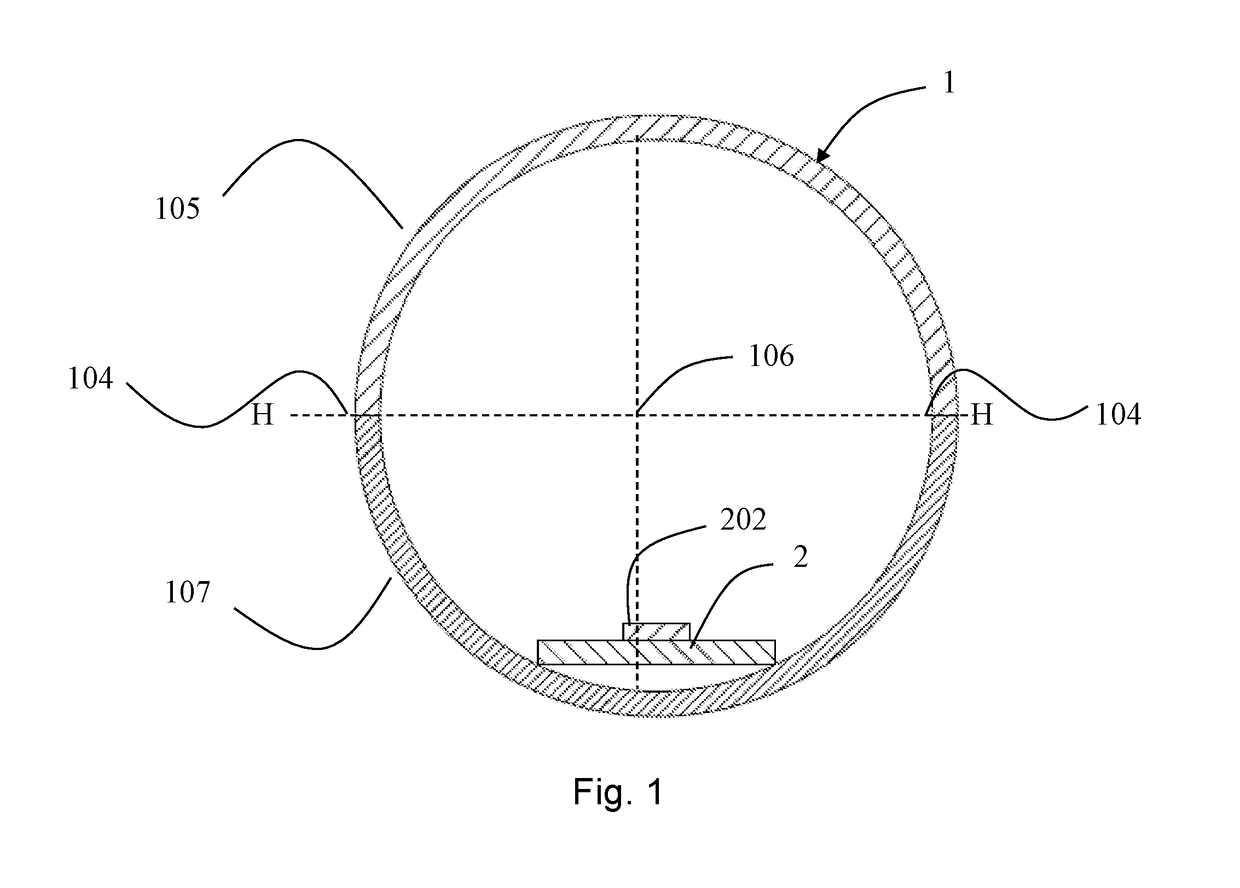
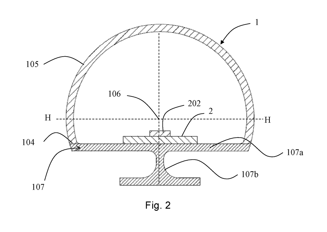
[0063]Referring to FIG. 1, in accordance with an exemplary embodiment of the claimed invention, the LED tube lamp comprises a lamp tube 1 and an LED light assembly. The lamp tube 1 includes a light transmissive portion 105 and a reinforcing portion 107. The reinforcing portion 107 is fixedly connected to the light transmissive portion 105.

[0064]The LED light assembly is disposed inside the lamp tube 1 and includes an LED light source 202 and an LED light strip 2. The LED light source 202 is thermally and electrically connected to the LED light strip 2, which is in turn thermally connected to the reinforcing portion 107. Heat generated by the LED light source 202 is first transmitted to the LED light strip 2 and then to the reinforcing portion 107 before egressing the lamp tube 1. Thermal connection is achieved with thermally conductive tapes or conventional mechanical fasteners such as screws aided by thermal grease to eliminate air gaps from interface areas.

[0065]Typically, the lam...


PUM

PropertyMeasurementUnit
field angleaaaaaaaaaa
roughnessaaaaaaaaaa
roughnessaaaaaaaaaa

Abstract

An LED tube lamp includes a lamp tube, which includes a light transmissive portion, a reinforcing portion and an end cap, and an LED light assembly, which includes an LED light source and an LED light strip. The light transmissive portion is fixedly connected to the reinforcing portion. The reinforcing portion includes a platform and a bracing structure fixedly connected to the platform and holds the platform in place. The bracing structure is made from a material having a greater stiffness than the material from which the lamp tube is made. The LED light source is thermally and electrically connected to the LED light strip, which is in turn thermally connected to the reinforcing portion. The end cap is attached to an end of the lamp tube. The light transmissive portion and the reinforcing portion define a first line between them on a cross section of the lamp tube.

Description

RELATED APPLICATIONS[0001]This is a continuation application of International Application PCT / CN2015 / 096501, with an international filing date of Dec. 5, 2015. The present application claims the benefit of the following Chinese Patent Applications: CN201410734425.5 filed Dec. 5, 2014; CN201510075925.7 filed Feb. 12, 2015; CN201510259151.3 filed May 19, 2015; CN201510324394.0 filed Jun. 12, 2015; CN201510373492.3 filed Jun. 26, 2015; CN201510448220.5 filed Jul. 27, 2015; CN 201510482944.1 filed Aug. 7, 2015; CN201510483475.5 filed Aug. 8, 2015; CN 201510499512.1 filed Aug. 14, 2015; CN201510555543.4 filed Sep. 2, 2015; CN 201510724263.1 filed Oct. 29, 2015; and CN201510882517.2 filed Dec. 4, 2015, each of which is incorporated herein by reference in its entirety.FIELD OF THE INVENTION[0002]The present invention relates to the features of LED incendiaries. More particularly, this invention describes various new and useful improvements for LED tube lamps.BACKGROUND OF THE INVENTION[000...

Claims


Application Information

Patent Timeline
Patent Type & Authority Patents(United States)
IPC IPC(8): F21K99/00F21K9/275F21V25/04F21K9/27F21V21/34F21V3/04F21Y103/10F21Y115/10
CPCF21K9/27F21V25/04F21V3/062F21K9/275F21Y2115/10F21Y2103/10F21V3/049F21V19/001
Inventor XU, HONGYANG, CHANGYOA, WENTAO
Owner JIAXING SUPER LIGHTING ELECTRIC APPLIANCE
Learn More