
Fan blade platform seal with leading edge winglet

a technology of leading edge winglet and fan blade, which is applied in the direction of leakage prevention, mechanical equipment, machines/engines, etc., can solve the problems of difficult sealing near the blade leading edge, weak sealing performance of flap-style fan blade platform seals, and difficult production of seals

Active Publication Date: 2018-06-05
RTX CORP
View PDF16 Cites 3 Cited by
  • Summary
  • Abstract
  • Description
  • Claims
  • Application Information

AI Technical Summary

Problems solved by technology

Generally, flap style fan blade platform seals have shown a weakness in sealing performance near the blade root leading edge.
Sealing near the blade leading edge has been problematic.
Additionally, the seals are difficult to produce since the seals are fabric reinforced for durability and strength.
Current manufacturing methods cannot produce seals with adequate fabric coverage for certain geometries.
This results in non-conforming hardware, difficulty bonding the seals to the platforms, and premature seal wear.
This geometry is not conducive to a seal which is subject to centrifugal loads.

Method used


Image

  • Fan blade platform seal with leading edge winglet
  • Fan blade platform seal with leading edge winglet
  • Fan blade platform seal with leading edge winglet

Examples


Embodiment Construction

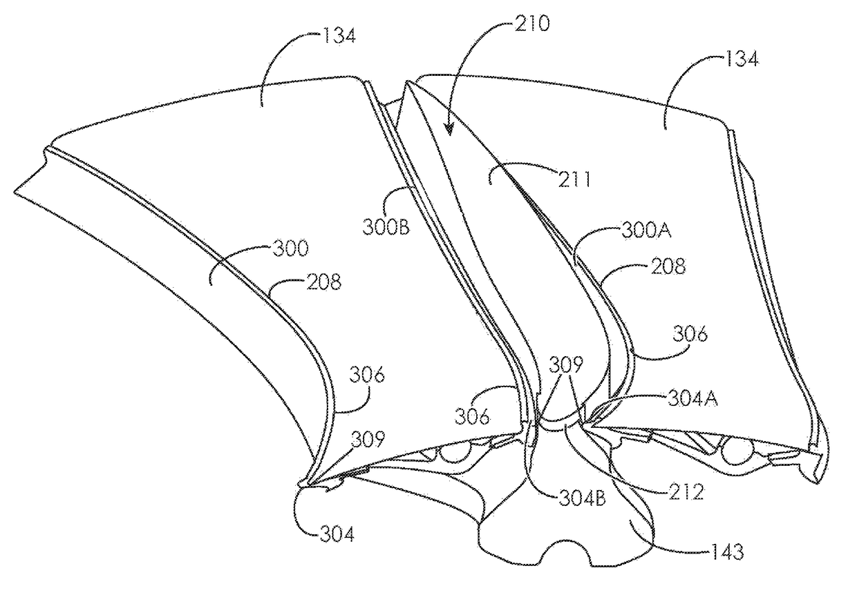
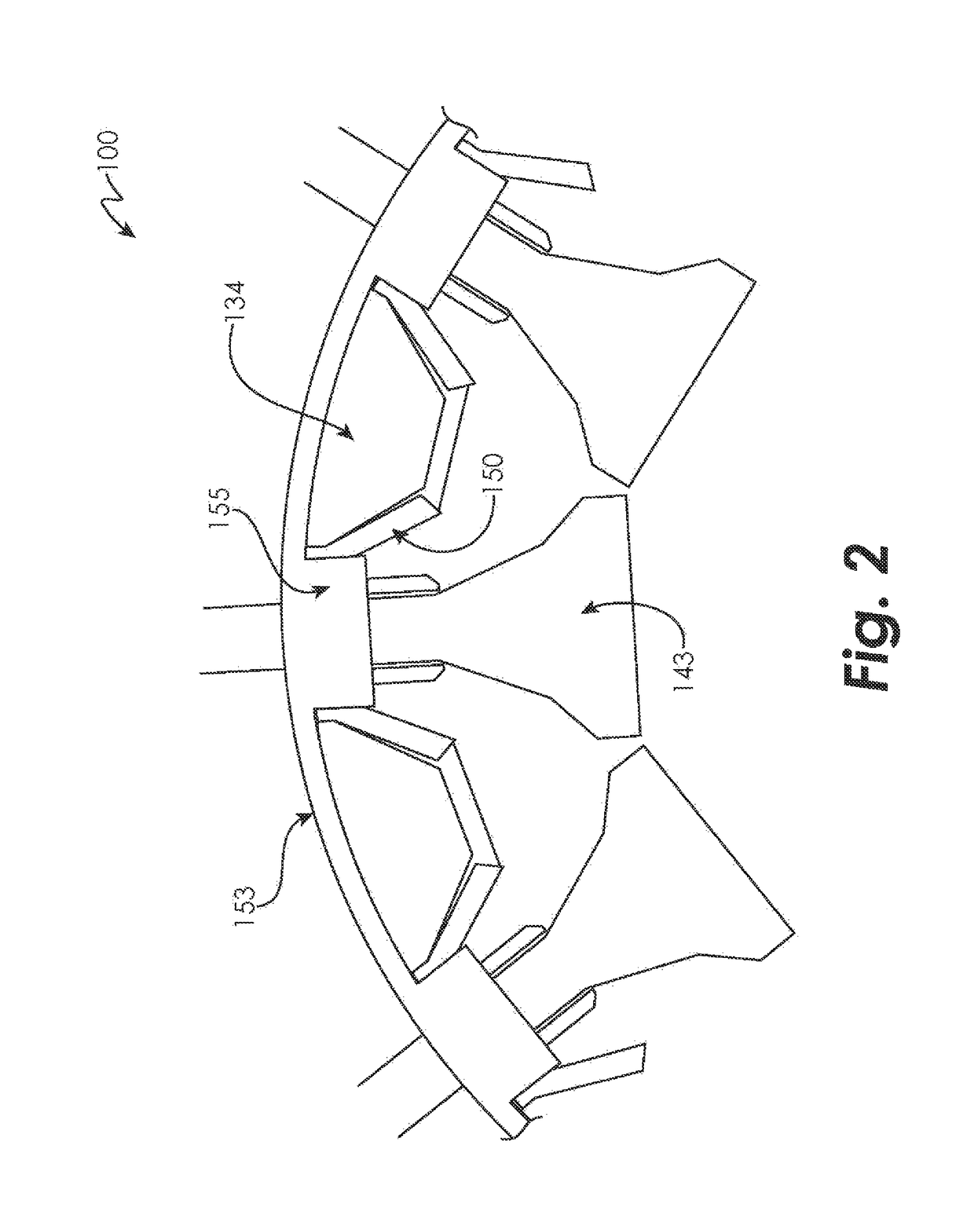
[0003]In one aspect, a fan section for a gas turbine engine is provided. The fan section includes a fan hub including a slot and a fan blade including an airfoil extending from a root to a tip. The airfoil has an airfoil leading edge and the root is received in the slot. A first platform is secured to the fan hub and arranged between adjacent fan blades. A first platform seal including a platform seal leading edge and a base is secured to a side of the first platform. A first winglet extends from the platform seal leading edge and contacts the airfoil leading edge.

[0004]In a further embodiment of the above, the fan section further includes a spinner including a castellated spinner seal. The first winglet contacts the castellated spinner seal.

[0005]In a further embodiment of any of the above, the fan section further includes a second platform and a second platform seal secured to the second platform. The second platform seal has a second winglet that contacts the first winglet.

[0006]...


PUM

PropertyMeasurementUnit
speedaaaaaaaaaa
speedaaaaaaaaaa
elastomericaaaaaaaaaa

Abstract

A fan section for a gas turbine engine is provided. The fan section having a fan hub with a slot and a fan blade with an airfoil extending from a root to a tip, the airfoil having a leading edge and the root is received in the slot, wherein a first platform is secured to the fan hub and arranged between adjacent fan blades of the fan section, the first platform having a first platform seal including a platform seal leading edge and a base is secured to a side of the first platform and a first winglet extends from the platform seal leading edge and contacts the airfoil leading edge.

Description

TECHNICAL FIELD OF THE DISCLOSED EMBODIMENTS[0001]The present disclosures relate generally to a gas turbine engine and, more particularly, to a fan blade platform platform seal with a leading edge winglet.BACKGROUND OF THE DISCLOSED EMBODIMENTS[0002]Generally, flap style fan blade platform seals have shown a weakness in sealing performance near the blade root leading edge. The platform seals by nature deflect significantly from their as-produced position when installed in the engine. Sealing near the blade leading edge has been problematic. Additionally, the seals are difficult to produce since the seals are fabric reinforced for durability and strength. Current manufacturing methods cannot produce seals with adequate fabric coverage for certain geometries. This results in non-conforming hardware, difficulty bonding the seals to the platforms, and premature seal wear. Moreover, near the leading edge, the fan blade geometry undercuts the fan platform. This geometry is not conducive t...

Claims


Application Information

Patent Timeline
Patent Type & Authority Patents(United States)
IPC IPC(8): F01D11/00F01D5/30F02K3/06
CPCF01D11/008F01D5/3023F02K3/06F05D2300/437F05D2220/36F05D2300/431
Inventor TATTON, ROYCE
Owner RTX CORP
Learn More