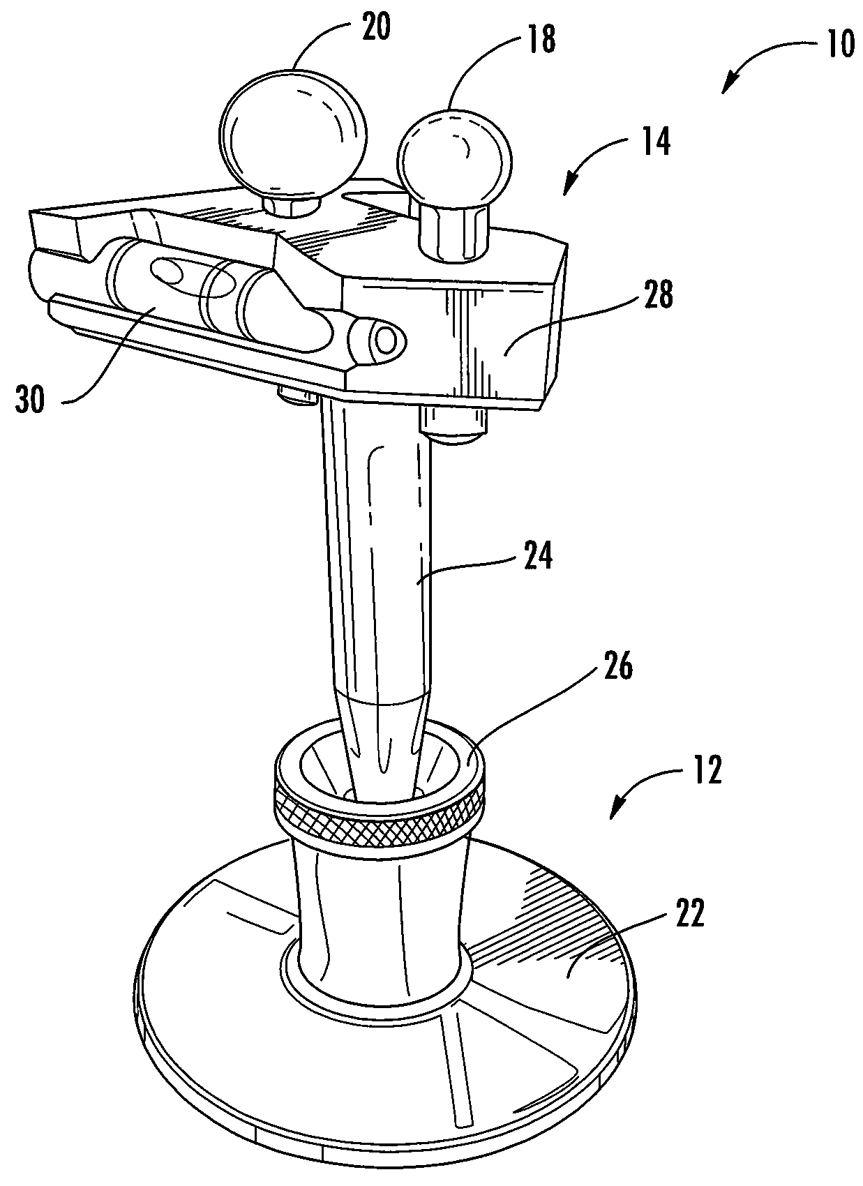
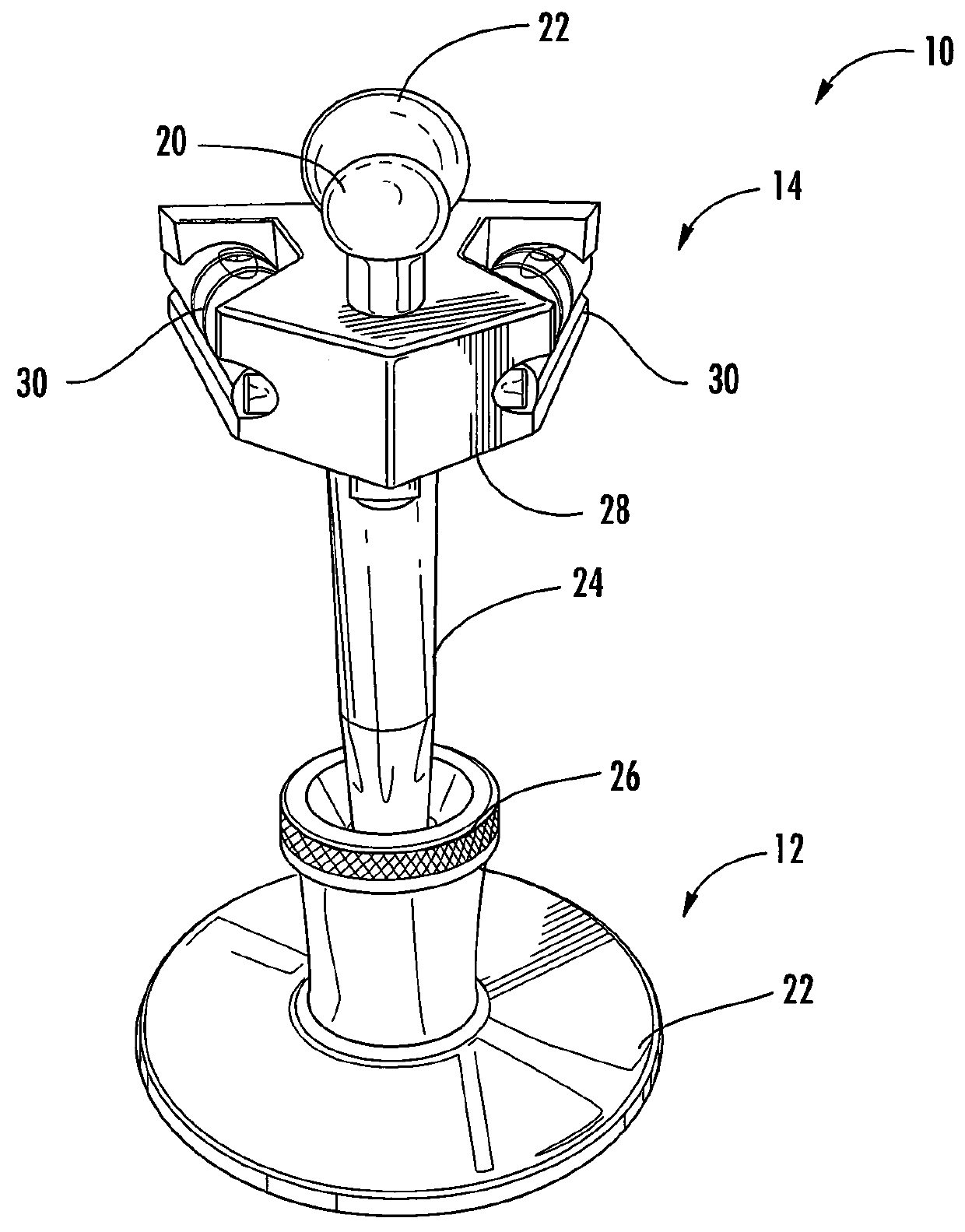
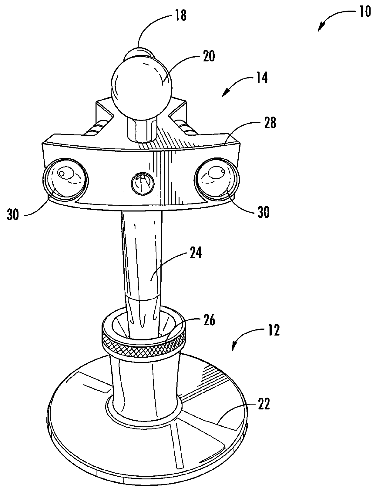
[0014]According to an embodiment of the present invention, referring to FIGS. 1-5, an eyeline sighting device 10 includes a base portion 12 supporting a top portion 14. The base portion 12 adjustably supports the top portion 14 on a working surface such as a cockpit dashboard 16. The top portion 14 includes first and second sighting elements 18 and 20. With the top portion 14 properly positioned on the base portion 12, a pilot or other user of the device 10 is able to readily verify eyeline by visual alignment of the first and second sighting elements 18 and 20.
[0015]The base portion 12 includes a mounting base 22, a shaft 24, and adjustment joint 26 between the mounting base 22 and the shaft 24. The overall height of the base portion 12 can be a fixed height to be optimal for a wide range of aircraft. In an alternate embodiment, a height adjustment mechanism can be incorporated in the base. In the depicted embodiment, the adjustment joint 26 includes a ball and socket joint, allowing omni-directional angling of the shaft 24 and top portion 12 relative to the mounting base 22 for leveling purposes. The adjustment joint 26 can compensate non-horizontal or otherwise irregular geometry of the cockpit dashboard.
[0016]The top portion 14 includes a frame 28 connected to the shaft 24 and carrying the first and second sighting elements 18 and 20, as well as at least one level indicator 30. In one embodiment, the frame 28 is shaped like an arrow that points to a user (e.g., a pilot) when properly oriented. The first and second sighting elements 18 and 20 can be round, cubical or other shapes. The second sighting element 20 is larger than the first sighting element 18 so it can be seen behind the first sighting element 18. The first and second sighting elements 18 and 20 can also have contrasting colors to facilitate visual alignment. For example, the first sighting element 18 is black and the second sighting element 20 is red.
[0017]The at least one level indicator 30 is used to adjust the position of the frame 28 relative to a horizontal plane such that the center of the first and second sighting elements 18 and 20 are in the same horizontal plane. In the depicted embodiment, the top portion 14 includes two tubular liquid level indicators 30 on two opposite sides of the frame 28 oriented not in parallel. The first and second sighting elements 18 and 20 are mounted on the top of the frame 28 along the center line of the frame 28, as shown in FIGS. 1-5. Other types of level indicators, such as digital levels can also be used.
[0018]The device 10 is made of combination of made from molded or formed metal, alloy, plastics, other appropriate materials, or combinations thereof.
[0019]Referring to FIG. 6, a method for positioning a pilot in an aircraft using the device 10 is illustrated. At step 602 the device 10 is placed on a working surface such as the cockpit dashboard of an aircraft, as shown in FIG. 5. The device 10 is positioned such that the frame 28 points at the pilot and the second sighting element 20 (larger element) will be visible behind the first sighting element 18 (smaller element).
[0020]At step 604, the frame 28 of the device 10 is leveled. For example, the frame 28 of the device 10 can be adjusted by manipulating the position of shaft 24 via the adjustment joint 26 to compensate non-horizontal or otherwise irregular geometry of the cockpit dashboard.
[0021]At step 606, the first sighting element and the second sighting element are visually aligned along the axis of view of the pilot such that the center of the first sighting element 18 and second sighting element 20 and the pilot's eye position are on the same horizontal plane, as shown in FIG. 7A.
[0022]At step 608, the height of the pilot's seat is adjusted based on the alignment. The height of the pilot's seating position needs to be increased when the first sighting element 18 blocks the top portion of the second sighting element 20, as shown in FIG. 7B. The height of the pilot's seating position needs to be decreased when the first sighting element 18 blocks the bottom portion of the second sighting element 20, as shown in FIG. 7C.
[0023]In the depicted embodiment, the eyeline sighting device is used in connection with establishing proper eyeline for an aircraft pilot. While this is believed to be a particularly advantageous application, it will be appreciated that the present invention could also facilitate eyeline verification for other purposes.
[0024]The embodiment described above is provided for exemplary and illustrative purposes. Those skilled in the art will appreciate that the present invention is not necessarily limited to such an embodiment. Rather, numerous modifications, and adaptations for particular circumstances, fall within the scope of the invention as herein shown and described and of the claims appended hereto.