Optical fiber holding device, optical dispersion-equalizer, and method of manufacturing optical fiber holding device

Inactive Publication Date: 2007-11-27
MITSUBISHI ELECTRIC CORP
View PDF41 Cites 2 Cited by
  • Summary
  • Abstract
  • Description
  • Claims
  • Application Information

AI Technical Summary

Benefits of technology

[0016]The present invention has been made to solve the above problems and an object thereof is to provide an optical fiber holding device, an optical dispersion-equalizer, and a method of manufacturing an optical fiber holding device, which facilitates positioning o

Problems solved by technology

However, since the diameter of the optical fiber is 125 μm or so (60 μm, for instance), accurate positioning and mounting of the grating 2 on the heater 3 is difficult and takes a lot of time What is worse, the both ends of the optical fiber 1 of the grating 2 are only secured after the position, and any fixations are not had to the grating 2.
But, the two orthogonal polarization modes undergo a change in thei

Method used


Image

  • Optical fiber holding device, optical dispersion-equalizer, and method of manufacturing optical fiber holding device
  • Optical fiber holding device, optical dispersion-equalizer, and method of manufacturing optical fiber holding device
  • Optical fiber holding device, optical dispersion-equalizer, and method of manufacturing optical fiber holding device

Examples


Example

First Embodiment

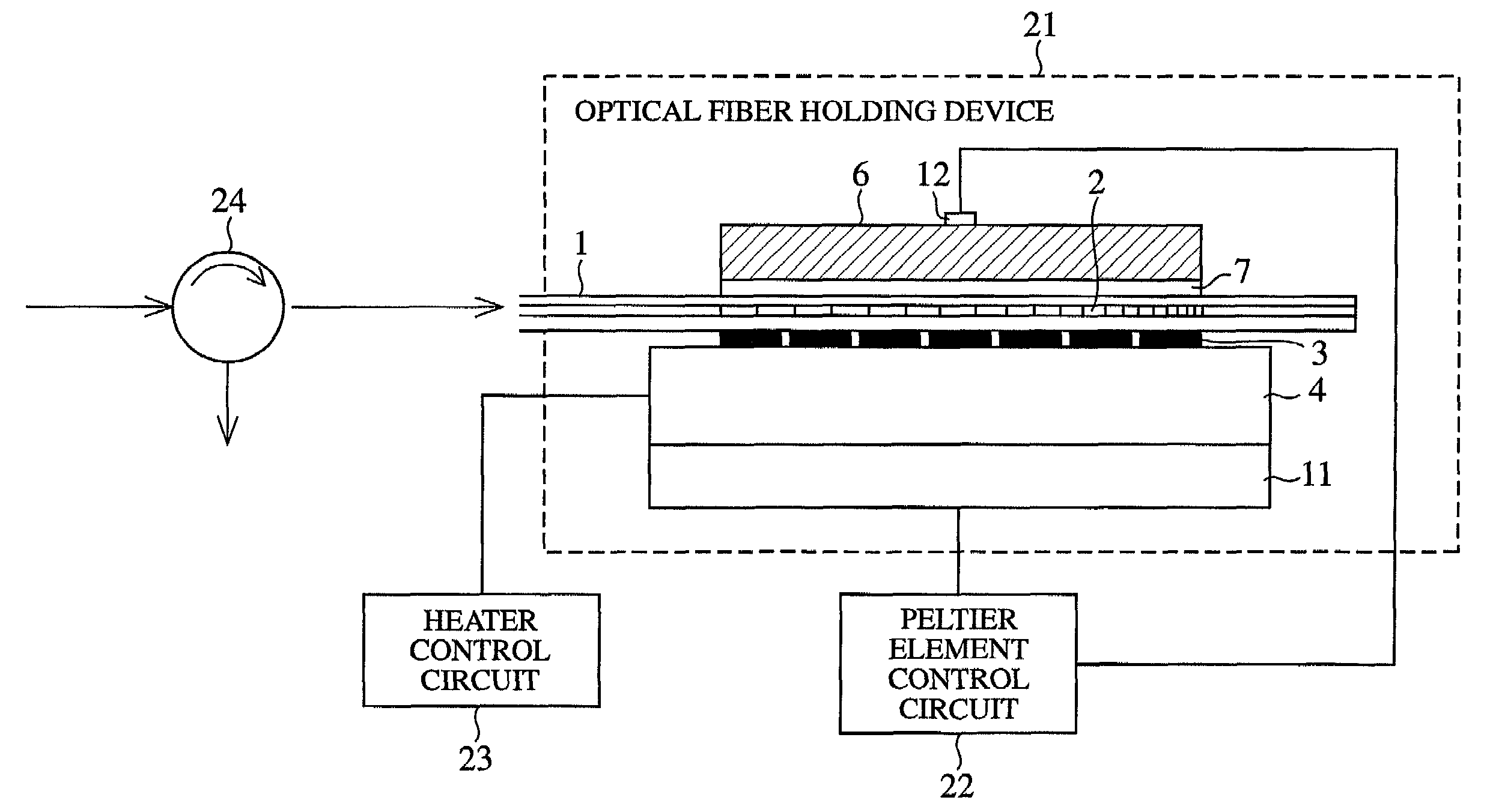
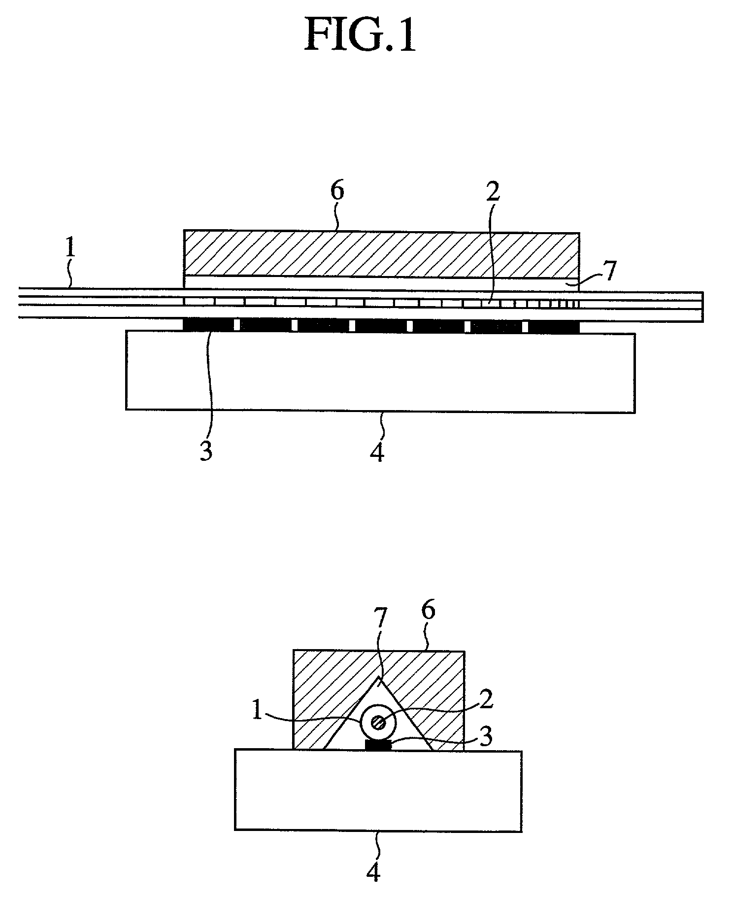
[0058]FIG. 1 is a structural drawing of an optical fiber holding device according to a first embodiment.

[0059]Referring to FIG. 1, reference numeral 6 denotes a strip-shaped member having a rectilinear V-shaped groove for accommodating therein an optical fiber 1; and 7 a gel substance as a filler filled in the V-shaped groove of the strip-shaped member. The other substance other than the above is the same as that shown in FIG. 14, and so the same reference numerals are used and descriptions thereof will be omitted for brevity sake.

[0060]As shown in FIG. 1, a gap is formed between the optical fiber I and a wall surface of the groove of the strip-shaped member 6 such that the optical fiber 1 is not contacted with the wall surface of the groove of the strip-shaped groove 6 in which the gel substance 7 is filled.

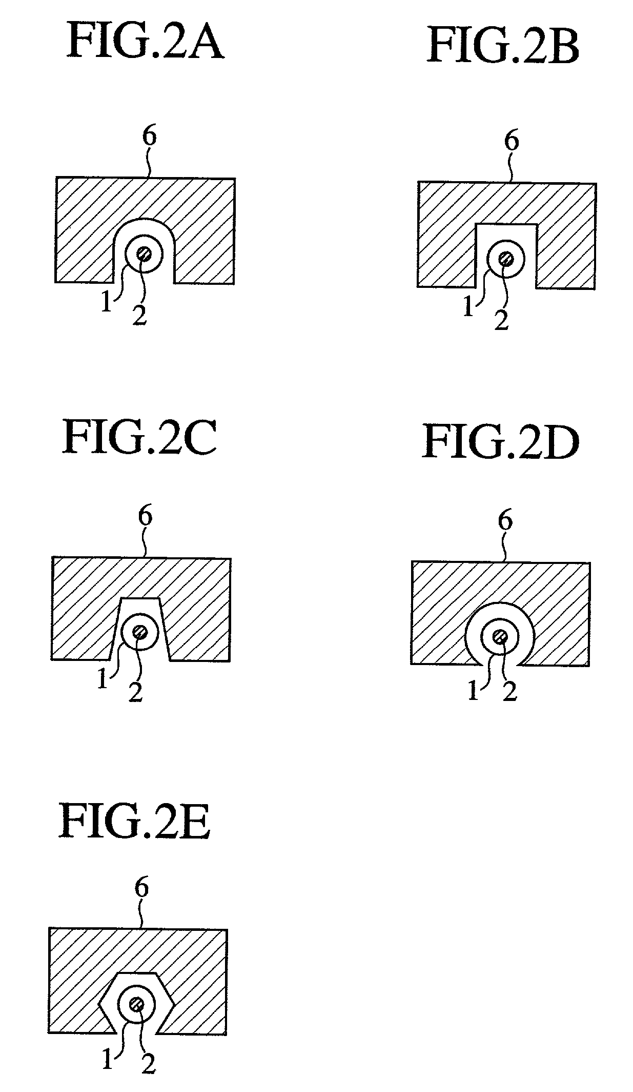
[0061]FIG. 2A is a variation of the strip-shaped member in which a groove is formed in U-shape. FIG. 2B is a variation of the strip-shaped member in which a groo...

Example

Second Embodiment

[0095]The optical fiber holding device according to a second embodiment shares the same structure in the first embodiment shown in FIGS. 1, 2, excepting its assembly procedures.

[0096]FIG. 10 is a flow chart showing assembly procedures of the optical fiber holding device according to a second embodiment.

[0097]At step ST 21, previously secure the strip-shaped member 6 on the substrate 4 on which the heater 3 is mounted. To this end, as shown in FIG. 5, the strip-shaped member 6 is mounted on the substrate 4 to the positioning marker of the strip-shaped member 6 provided on the substrate 4.

[0098]At step ST 22, fill the gel substance 7 in the strip-shaped member 6 secured on the substrate 4. To this end, the gel substance 7 is supplied through the micro dispenser in which the gel substance 7 is filled from the one end of the strip-shaped member 6 in the longitudinal direction. The gel substance 7 is filled in the groove of the strip-shaped member 6 with the aide of surf...

Example

Third Embodiment

[0104]The optical fiber holding device according to a third embodiment shares the same structure in the second embodiment shown FIGS. 1, 2, excepting its assembly procedures.

[0105]FIG. 11 is a flow chart showing assembly procedures of the optical fiber holding device according to a third embodiment.

[0106]At step ST 31, mount the optical fiber 1 on the heater 3 in such a manner that the both ends of the heater 3 are put on the positioning marker of the grating 2 which is placed on the surface of the optical fiber 1 at the both ends of the grating 2. To this end, in order to linearly mount the optical fiber 1 on the heater 3, the optical fiber 1 at the both ends of the grating 2 is held with a holing mechanism and the holding mechanism is moved in the longitudinal direction with a driving system. Then, with a position detecting mechanism for a CCD image analysis, the both ends of the heater 3 are put on the positioning marker of the grating 2 which is placed on the sur...


PUM


Abstract

There is disclosed an optical fiber holding device comprising an optical fiber 1 with a grating 2 for reflecting a propagated optical signal of a number of wavelengths, a heater 3 for heating the grating 2 to a predetermined temperature distribution, a strip-shaped member 6 having a rectilinear groove in which the optical fiber 1 is accommodated, and the gel substance 7 contacting with the optical fiber 1 is filled, and a substrate 4 on which the heater 3 and the strip-shaped member 6 are mounted.

Description

BACKGROUND OF THE INVENTION[0001]1. Field of the Invention[0002]This invention relates to an optical fiber holding for holding an optical fiber for an optical fiber communication system, an optical dispersion-equalizer for compensating wavelength dispersion of a number of optical signals propagating through the optical fiber, and a method of manufacturing the optical fiber holding device.[0003]2. Description of Related Art[0004]FIG. 14 is a structural drawing of a conventional optical fiber holding device.[0005]Referring to FIG. 14, reference numeral 1 denotes an optical fiber made of a core and a clad; 2 a grating which is formed at a part of the core of the optical fiber and reflects an optical signal of a number of wave lengths; 3 heaters which are made of a thin film for heating the grating to a predetermined temperature distribution; and 4 a substrate which is, for instance, made of quartz and on which the heater 2 is mounted. Furthermore, the grating 2 is used for compensating...

Claims


Application Information

Patent Timeline
IPC IPC(8): G02B6/00G02B6/26G02B6/36G02B6/42G02B6/02G02B6/34G02F1/01
CPCG02B6/29322G02B6/29394G02B6/3636G02B6/29395G02B6/02204G02B6/364G02B6/29398G02B6/02
Inventor HASHIMOTO, TAKASHIHASHIMOTO, MINORU
Owner MITSUBISHI ELECTRIC CORP
Why Eureka
Try Eureka