

Selectable rotary sprayer
- Summary
- Abstract
- Description
- Claims
- Application Information
AI Technical Summary
Benefits of technology
Problems solved by technology
Method used
Image

Examples
Embodiment Construction
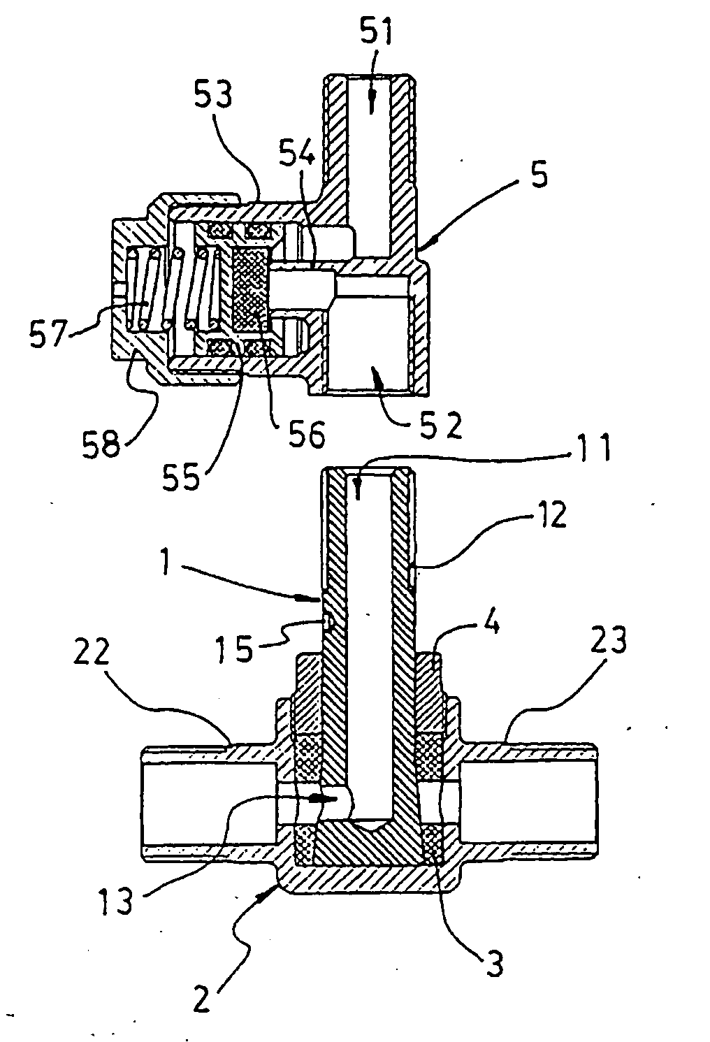
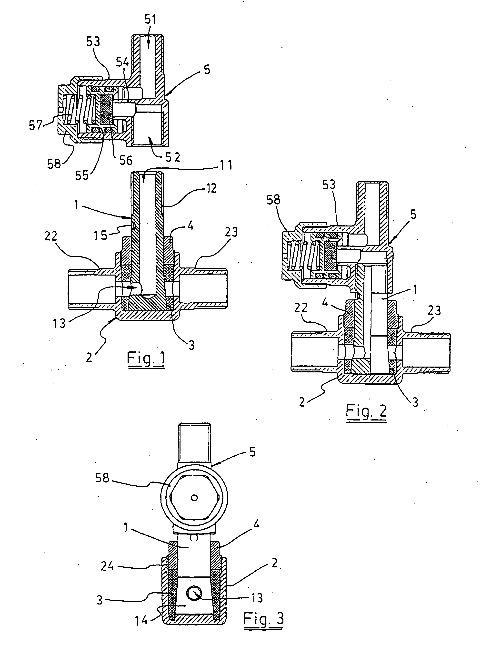
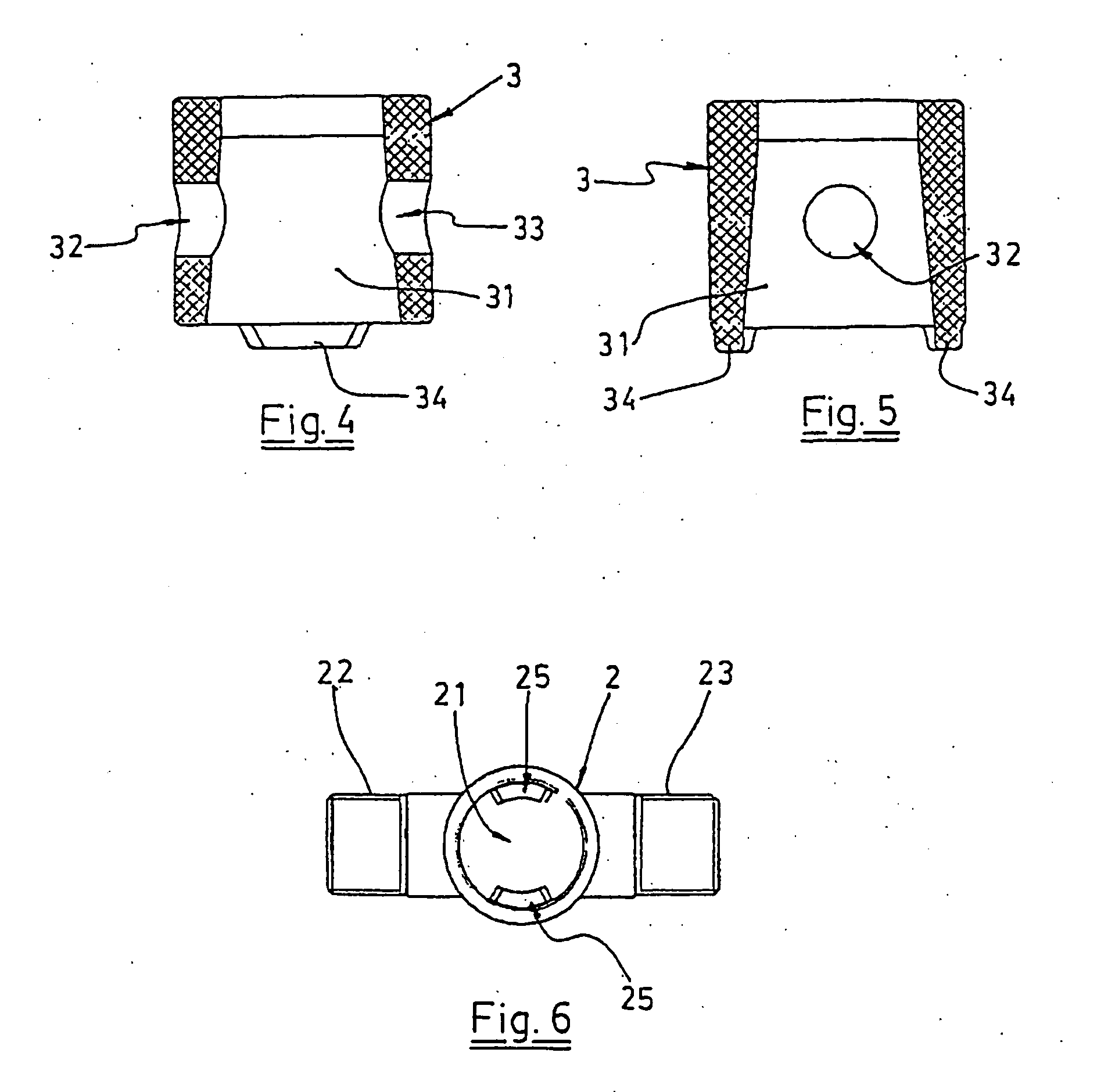
[0008] The selectable rotary sprayer of this invention is of the type first mentioned above, namely, it comprises: [0009] a shaft provided with an axial inlet and a radial outlet; [0010] a rotary body provided with two radial outlets; [0011] sealing means mounted between the shaft and the rotary body; and [0012] a non-drip valve;
and has constructive particularities for reducing the number of parts forming the present sprayers, with a consequent reduction of manufacturing cost, and for preventing the appearance of leaks between the shaft and the rotary body, with the possibility of voluntarily selection of the tightening or frictional force that is desired to prevent the undesired rotation of the rotary body.
[0013] According to the invention, the selectable rotary sprayer comprises: [0014] a shaft having, in correspondence with the end provided with the radial outlet, a frustoconical portion widening towards the free end of the shaft and for being received in the central cavity of...
PUM
 Abstract
Description
Claims
Application Information