Medical x-ray imaging apparatus

Active Publication Date: 2013-02-14
PLANMED OY
View PDF0 Cites 2 Cited by
  • Summary
  • Abstract
  • Description
  • Claims
  • Application Information

AI Technical Summary

Benefits of technology

[0006]Especially, the object of the invention is an arrangement which can facilitate patient positioning e.g

Problems solved by technology

Conventionally, a device group of its own consists of large-size and extremely expensive computed tomography apparatuses where the patient is typically positioned for imaging in the recumbent position within a ring-shaped or tubular structure.
As conventional computed tomography apparatuses have been quite massive and expen

Method used


Image

  • Medical x-ray imaging apparatus
  • Medical x-ray imaging apparatus
  • Medical x-ray imaging apparatus

Examples


Example

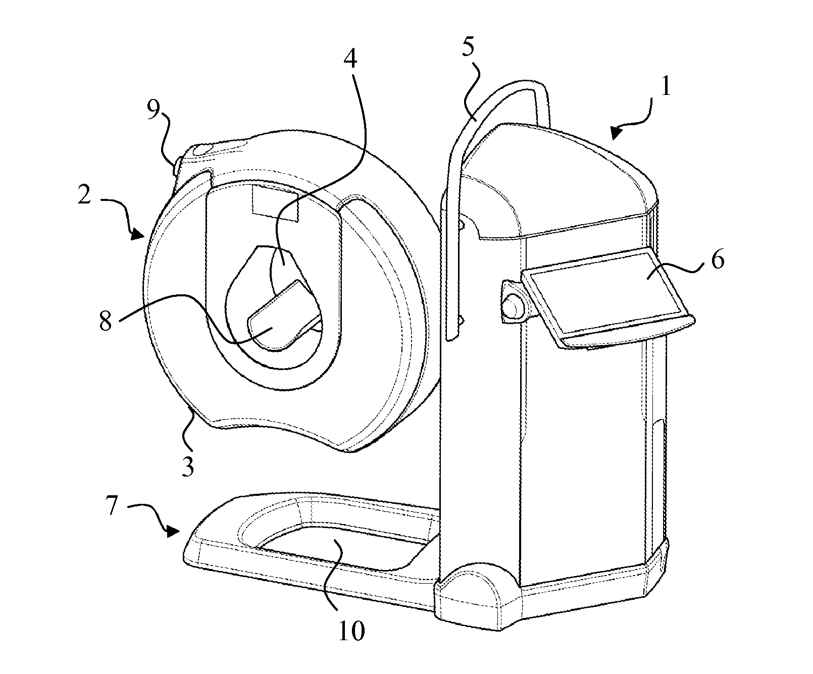
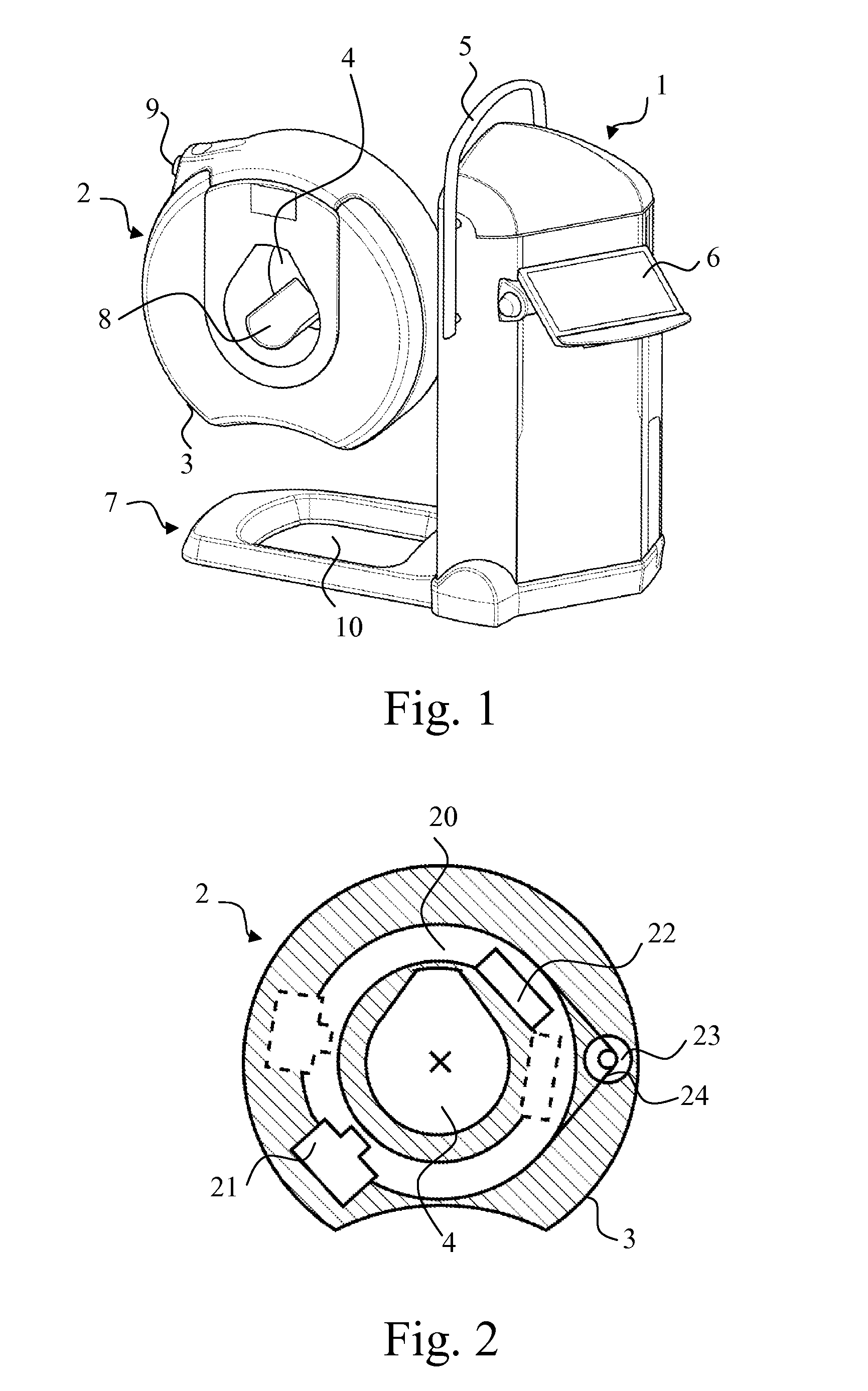
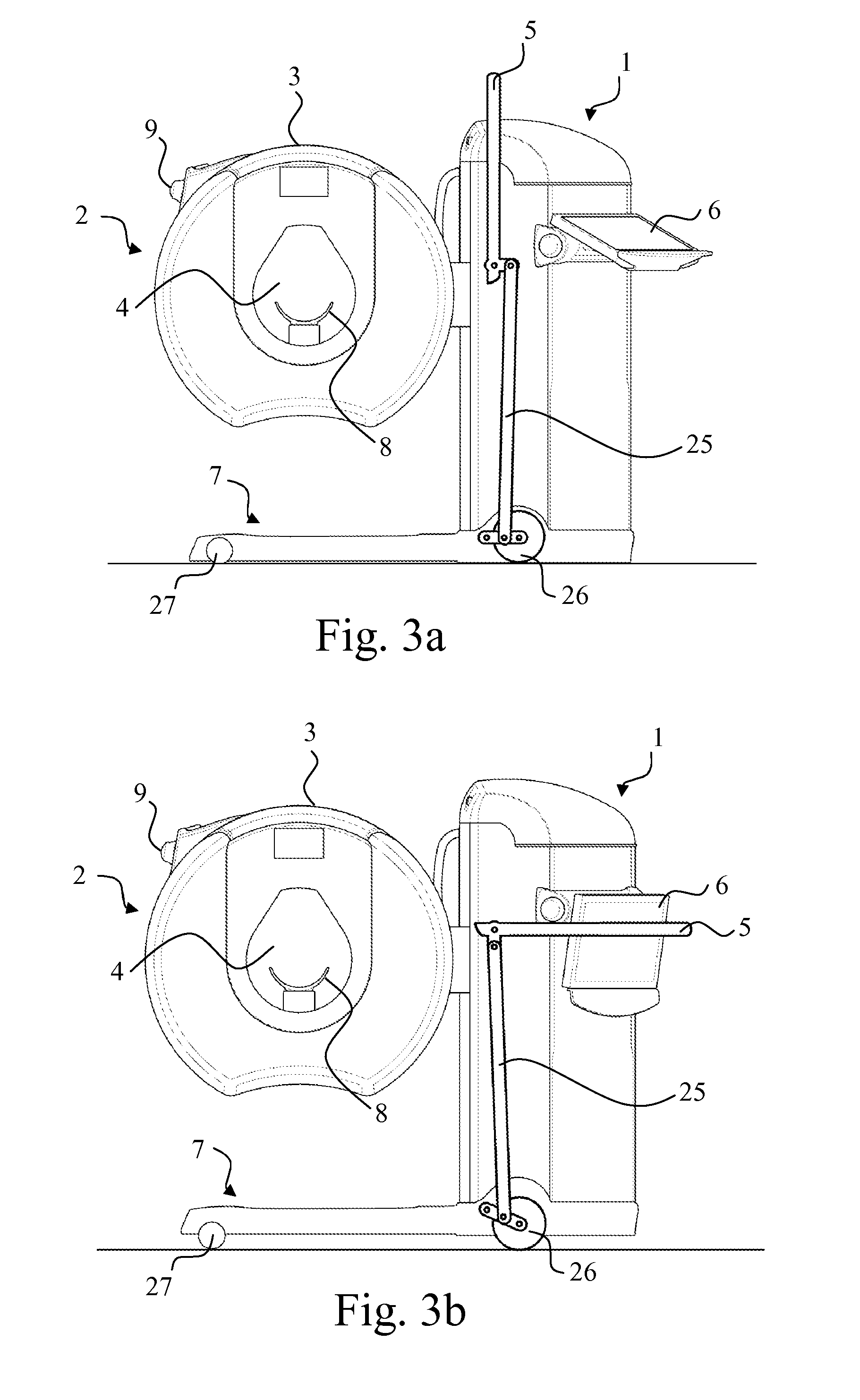
[0013]In the following, the terms centre and central axis will be used in connection with structures which do not necessarily form a true, full circle but are of circular shape only for their prevailing part. To avoid ambiguity, these terms refer in connection with this specification to a point and an axis which would be the centre or central axis of the structure in question in case that structure would form a full circle.

[0014]Furthermore, concerning one component of the apparatus according to the invention, this specification employs terms a substantially ring-shaped structure and an O-arm. When the dimension in the direction of the central axis of this structure can be significantly large with respect to the diameter of the ring-shaped structure in question, for the avoidance of doubt it is stated that in the following, vertical position of the O-arm refers to a position where the central axis of the O-arm is horizontally oriented and horizontal position of the O-arm refers to a...


PUM


Abstract

The invention relates to a medical x-ray imaging apparatus which includes a support construction (1) supporting a substantially ring-shaped structure (2), an O-arm (2), which in turn supports imaging means (21, 22) and which O-arm (2) is arranged with an examination opening (4). The imaging means (21, 22) are arranged movable within the O-arm (2). The cross-section of an outer cover (3) of the O-arm (2) in a direction perpendicular with respect to the central axis of the O-arm is arranged for its predominant portion substantially of the shape of an arch of a circle but to comprise a cut, within the sector covered by which cut the distance from the centre of said arch of the circle to the edge of the outer cover (3) is shorter than within the portion of the outer cover (3) being substantially of the shape of an arch of a circle.

Description

FIELD OF INVENTION[0001]The invention relates to a medical x-ray imaging apparatus according to the preamble of claim 1.BACKGROUND OF INVENTION[0002]Conventional apparatuses employed in medical x-ray imaging most simple of their basic structure comprise a source of radiation which is used together with a film cassette separate from the source of radiation. Hospitals commonly use also the so-called C-arch x-ray apparatuses where the source of radiation and the receiver of image information are arranged at the opposite ends of the arched arm part. Conventionally, a device group of its own consists of large-size and extremely expensive computed tomography apparatuses where the patient is typically positioned for imaging in the recumbent position within a ring-shaped or tubular structure.[0003]Computed tomography apparatuses have also been developed into more lightweight versions. As an example of prior art arrangements, we refer to U.S. Pat. Nos. 7,108,421 and 7,388,941. In such appara...

Claims


Application Information

Patent Timeline
IPC IPC(8): A61B6/03
CPCA61B6/035A61B6/032A61B6/0471A61B6/4085A61B6/4435A61B6/03
Inventor SEPPALA, LAURILAUKKANEN, TAPIOHYVARINEN, PENTTI
Owner PLANMED OY
Why Eureka
Try Eureka