Protecting cap for terminal consolidation splice

a terminal consolidation and protection cap technology, applied in the direction of insulated conductors, cable terminations, cables, etc., can solve the problems of difficult to confirm the position of the lower end of the splice portion from the inner surface of the bottom portion, and troublesome ruler use for measuring and examination

Active Publication Date: 2018-06-12
SUMITOMO WIRING SYST LTD
View PDF18 Cites 2 Cited by
  • Summary
  • Abstract
  • Description
  • Claims
  • Application Information

AI Technical Summary

Benefits of technology

[0011]The present design has been made in light of the problems described above, in which a first problem to be solved is making it possible to easily and accurately confirm an examination position in a dip molded protecting cap in which variation in the thickness of the closed bottom is likely to occur.
[0012]Also, a second problem to be solved is making it possible to avoid liquid leakage in which water sealant filled into the protecting cap spills out in a state where a splice portion has been inserted.
[0016]As described above, when using a protecting cap to which a control line that can be visually observed from the outside has been attached, if the position of the lower end of the consolidation splice portion is at a position at or below the control line on the bottom portion side, it is possible to perform an external visual observation and examination as to whether the consolidation splice portion and the stripped portion of the electrical wires that are continuous with the consolidation splice portion, as well as a required range of the insulating sheathed portion that is continuous with the stripped portion have been submerged in the water sealant. In other words, if the position of the lower end of the consolidation splice portion has floated up past the control line and is on the opening side, it can be determined that the necessary portions have not been submerged in the water sealant and that the product is defective. In this way, a defective product can be easily and accurately determined through an external visual examination.
[0023]A peripheral wall extends straight in the length direction from the bottom portion to a vicinity of the opening, and an enlarged diameter portion that widens to incline in a range of 3 to 6 degrees toward the opening in the peripheral wall is provided in the vicinity of the opening, a gap being formed between an inner surface of the enlarged diameter portion and an outer circumferential surface of an insulating sheathed portion of the wire harness, to prevent the water sealant from reaching the opening due to capillary action.
[0027]Employing a protecting cap that has a control line for water sealant, which is in the dip molded protecting cap according to the first embodiment, and is provided with an enlarged diameter portion for preventing the water sealant from leaking out, due to capillary action, on the insertion opening side according to the second embodiment is favorable in terms of production cost and performance.
[0029]Also, in the protecting cap according to the second embodiment, because an enlarged diameter portion is provided in the peripheral wall on the opening side and a gap widens between the enlarged diameter portion and the outer circumference of the inserted wire harness, movement of the water sealant due to capillary action that results in spilling out from the opening can be prevented.

Problems solved by technology

Insulation protection is required because a short circuit occurs when the splice portion comes into contact with another conductive material, and water sealing processing is required because corrosion occurs if water adheres to the splice portion, particularly if the splice portion is to be arranged in a submersion area.
As described above, the work of using a ruler for measurement and examination is troublesome and variations may occur between workers.
Also, a second problem to be solved is making it possible to avoid liquid leakage in which water sealant filled into the protecting cap spills out in a state where a splice portion has been inserted.
Specifically, if the water sealant that is filled into a transparent protecting cap is transparent, it is difficult to visually confirm a boundary between the inner surface of the bottom portion of the protecting cap and the lower surface of the water sealant from the outside, and thus when a non-transparent control line is provided in advance, suitable and defective products can be determined at a glance by using the control line as a reference.
Because the water sealant is filled into the dip molded protecting cap that is colorless and transparent, it is hard to visually observe the portion filled by water sealant from the outside, and variation in the thickness of the bottom portion of the protecting cap is likely to occur, and therefore it is hard to confirm the position of the lower end of the splice portion from the inner surface of the bottom portion.

Method used


Image

  • Protecting cap for terminal consolidation splice
  • Protecting cap for terminal consolidation splice
  • Protecting cap for terminal consolidation splice

Examples


Embodiment Construction

[0038]Embodiments of the present design will be described below with reference to the diagrams.

[0039]FIGS. 1 to 4C show a protecting cap according to a first embodiment.

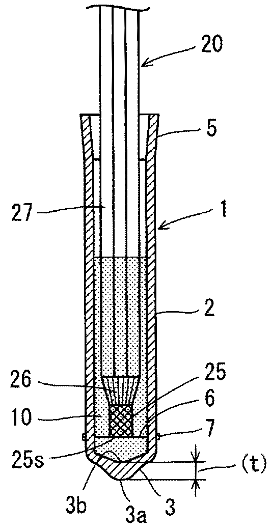
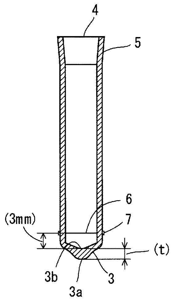
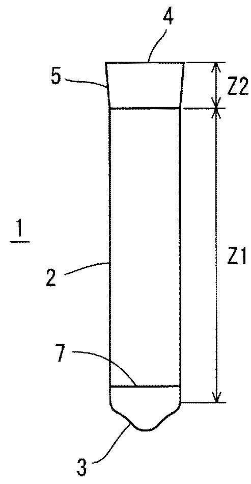
[0040]A protecting cap 1 is a dip molded tubular body that is colorless and transparent, to which a bottom portion 3 is provided at one end in the length direction of a peripheral wall 2 of the tubular body, and an opening 4 for insertion is provided at the other end. The peripheral wall 2 has an annular cross section, and with a region Z1 from the bottom portion 3 to the vicinity of the opening 4 being a straight tube with the same cross-sectional shape, a region Z2 from the upper end of the region Z1 in FIG. 1A to the opening 4 is an enlarged diameter portion 5 that widens towards the opening.

[0041]As shown in FIG. 2, a colorless and transparent water sealant 10 is filled into the protecting cap 1 and a terminal consolidation splice portion 25 (hereinafter referred to as “splice portion 25”) provided at the termina...


PUM

PropertyMeasurementUnit
diameteraaaaaaaaaa
diameteraaaaaaaaaa
lengthaaaaaaaaaa

Abstract

A water proofing protecting cap that is placed over a terminal consolidation splice portion of a wire harness. The protecting cap being a dip molded transparent tubular body that is provided with a bottom portion wherein, from an opening for insertion at the other end, the protecting cap can be filled with a water sealant and a terminal consolidation splice portion of a wire harness is insertable. A marking line made by a rib on a male mold used in the dip molding is provided in a circumferential direction on an inner circumferential surface of a peripheral wall and is distanced by a required height from an inner surface of the bottom portion toward the opening, and a non-transparent line is provided on an outer circumferential surface of the peripheral wall following the marking line. The non-transparent line serving as a control line for a lower end position of the consolidation splice portion.

Description

CROSS REFERENCE TO RELATED APPLICATIONS[0001]This application claims the priority of Japanese patent application JP2014-257965 filed on Dec. 19, 2014, the entire contents of which are incorporated herein.TECHNICAL FIELD[0002]The present invention relates to a protecting cap for a terminal consolidation splice, and particularly to a protecting cap that is placed over a terminal consolidation splice, which is formed by welding or crimping together electrical wire terminals of core wires of a plurality of electrical wires in a wire harness, for insulation protection and water-proofing, in which the filling amount of water sealant filled into the protecting cap can be easily checked and water sealant can be reliably prevented from spilling out.BACKGROUND ART[0003]Of the many electrical wires that constitute a wire harness, the plurality of electrical wires that require circuit connection are stripped of their sheathed portion at their electrical wire terminals, and the exposed core wire...

Claims


Application Information

Patent Timeline
Patent Type & Authority Patents(United States)
IPC IPC(8): H01B17/38H01R4/22H02G15/04
CPCH02G15/043H01R4/22H01B17/38H01B7/282H01R4/70Y02A30/14
Inventor FUKUDA, TAKAO
Owner SUMITOMO WIRING SYST LTD
Why Eureka
Try Eureka