Vibration damping device and method of manufacturing the same

Pending Publication Date: 2022-09-22
TOKAI RUBBER IND LTD +1
View PDF0 Cites 0 Cited by
  • Summary
  • Abstract
  • Description
  • Claims
  • Application Information

AI Technical Summary

Benefits of technology

The present invention provides a vibration damping device with a unique structure that can accurately confirm if the device is securely attached to the bracket. The device includes inspection flat surfaces that are parallel to each other, making it easy to measure the position of the device using a machine. This helps to prevent the device from becoming dislodged from the bracket. The method of manufacturing the device is simple and efficient, reducing labor and time required for inspection. The technical effects of this invention are stable and secure attachment of the vibration damping device to the bracket, improved accuracy of inspection, and simplified manufacturing process.

Problems solved by technology

However, as in JP-A-2018-162824, if the detent structure for preventing the vibration-damping device main unit from becoming dislodged from the bracket is provided in the mounting space of the bracket, for example, when the vibration-damping device main unit is inserted and attached to the mounting space of the bracket, it is difficult to accurately grasp engagement failure in which the engaging parts are not engaged in an appropriate state.
However, with the through hole provided in the forward wall of the bracket, the engaging face is hidden by the claw-shaped engaging part, making it difficult to confirm the engaged state.
Thus, visually confirming the dark and narrow engaged portion inside the through hole per se is difficult.
For example, it is substantially impossible to find a defect such as a crack generated on a surface other than the visible surface.

Method used


Image

  • Vibration damping device and method of manufacturing the same
  • Vibration damping device and method of manufacturing the same
  • Vibration damping device and method of manufacturing the same

Examples


Embodiment Construction

[0034]A practical embodiment of the present invention will be described below in reference to the drawings.

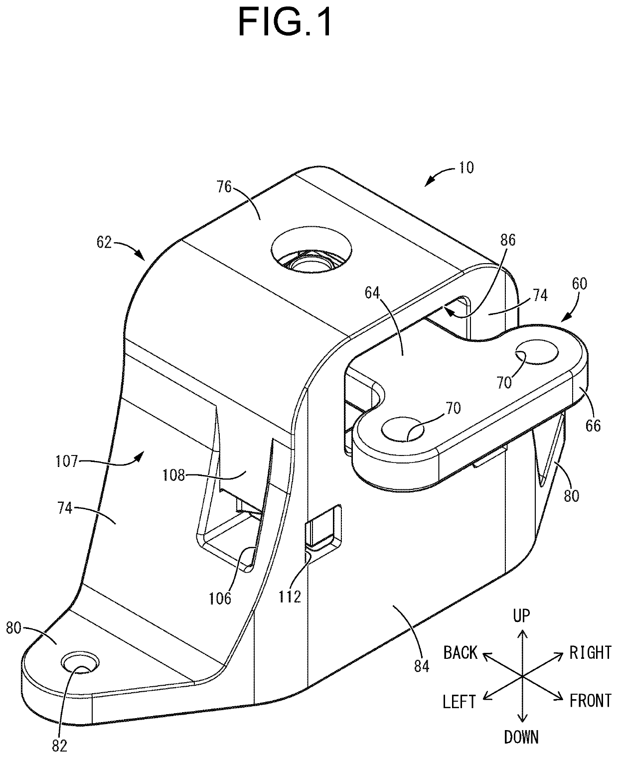
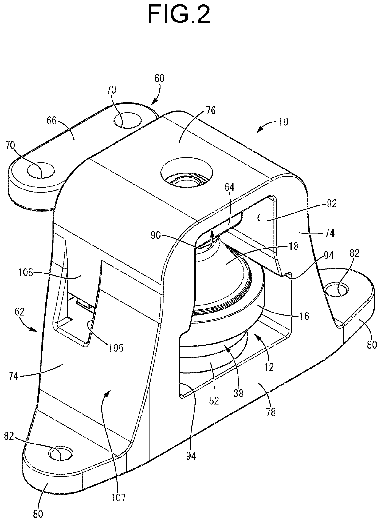
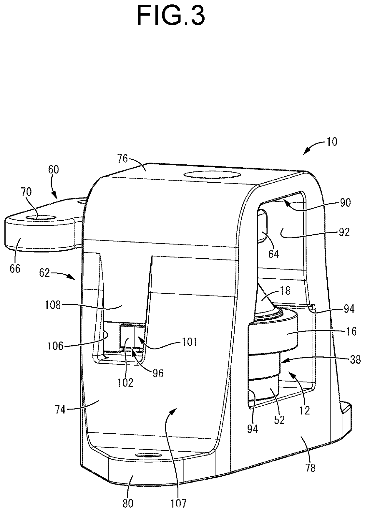
[0035]Referring first to FIGS. 1 to 6, there is depicted an automotive engine mount 10 as a first practical embodiment of a vibration damping device according to the present invention. The engine mount 10 includes a mount main unit 12 serving as a vibration-damping device main unit. As shown in FIG. 7, the mount main unit 12 has a structure in which a first mounting member 14 and a second mounting member 16 serving as a fixture member are connected by a main rubber elastic body 18. In the following description, as a general rule, the vertical direction refers to the vertical direction in FIG. 4, which coincides with the mount center axis direction, and the left-right direction refers to the left-right direction in FIG. 4, which coincides with the width direction of an outer bracket 62 to be described later. Besides, as a general rule, the front-back direction refers to the left...


PUM


Abstract

A vibration damping device including a vibration-damping device main unit inserted into a mounting space of a bracket from a lateral side and securely supported by the bracket. The bracket includes engaging pieces on respective opposed inside faces of the mounting space, and engaging action of the engaging pieces with respect to respective detent engaging faces formed on a fixture member of the vibration-damping device main unit prevents the vibration-damping device main unit from becoming dislodged from the mounting space of the bracket. Opposed walls of the mounting space are each penetrated by an aperture window, and inspection flat surfaces are separately provided to an outside surface of each engaging piece visible from an outside through the aperture window and a corresponding external side surface of the bracket that is off the aperture window. The inspection flat surfaces are parallel to each other.

Description

INCORPORATED BY REFERENCE[0001]The disclosure of Japanese Patent Application No. 2021-047685 filed on Mar. 22, 2021 including the specification, drawings and abstract is incorporated herein by reference in its entirety.BACKGROUND OF THE INVENTION1. Field of the Invention[0002]The present invention relates to a vibration damping device for use in, for example, an automotive engine mount or the like, and a method of manufacturing the same.2. Description of the Related Art[0003]Conventionally, for example, a vibration damping device having a structure in which a bracket is attached to the vibration-damping device main unit is used, for example, in an engine mount for an automobile. As shown in Japanese Unexamined Patent Publication No. JP-A-2018-162824, the bracket has a mounting space into which the vibration-damping device main unit is inserted from the lateral side, and the vibration damping device has a structure in which a fixing member of the vibration-damping device main unit is...

Claims


Application Information

Patent Timeline
IPC IPC(8): B60K5/12F16F15/08
CPCB60K5/1208F16F15/08F16F2230/0005F16F13/00F16F13/10B60K5/12G01M13/00F16F2226/04F16F13/103
Inventor OKI, KENJITANAKA, SHINGOKONDO, HIROKIARAI, YUSUKEKUBOTA, KOZO
Owner TOKAI RUBBER IND LTD
Why Eureka
Try Eureka