Stator structure

a technology of stator and spherical structure, which is applied in the direction of dynamo-electric machines, magnetic circuit shapes/forms/construction, electrical equipment, etc., can solve the problems of affecting the working performance, affecting the operation efficiency, and the electrical equipment often generates high heat, so as to reduce eddy loss, enhance the operation efficiency of the motor, and increase the magnetic induction area

Active Publication Date: 2018-06-12
ASIA VITAL COMPONENTS SHENZHEN CO LTD
View PDF17 Cites 0 Cited by
  • Summary
  • Abstract
  • Description
  • Claims
  • Application Information

AI Technical Summary

Benefits of technology

[0008]It is therefore a primary object of the present invention to provide a stator structure, which is able to enhance the operation efficiency of the motor.
[0009]It is a further object of the present invention to provide the above stator structure, which is able to greatly lower the manufacturing cost.
[0010]It is still a further object of the present invention to provide the above stator structure, which is able to reduce eddy loss.
[0012]According to the structural design of the present invention, in operation of the fan, the protrusion blocks formed on the extension section serve to increase the magnetic induction area of the main body to enhance the operation efficiency of the motor. In addition, the protrusion blocks and the recesses are alternately arranged to reduce eddy loss.

Problems solved by technology

In operation, the electronic equipment often generates high heat at the same time to affect the working performance or even lead to shutdown of the electronic equipment.
However, the additional silicon steel sheets will lead to increase of cost. FIG. 1 is a perspective assembled view of a conventional stator structure.
However, this measure is likely to lead to the problem of eddy loss.

Method used


Image

  • Stator structure
  • Stator structure
  • Stator structure

Examples


Embodiment Construction

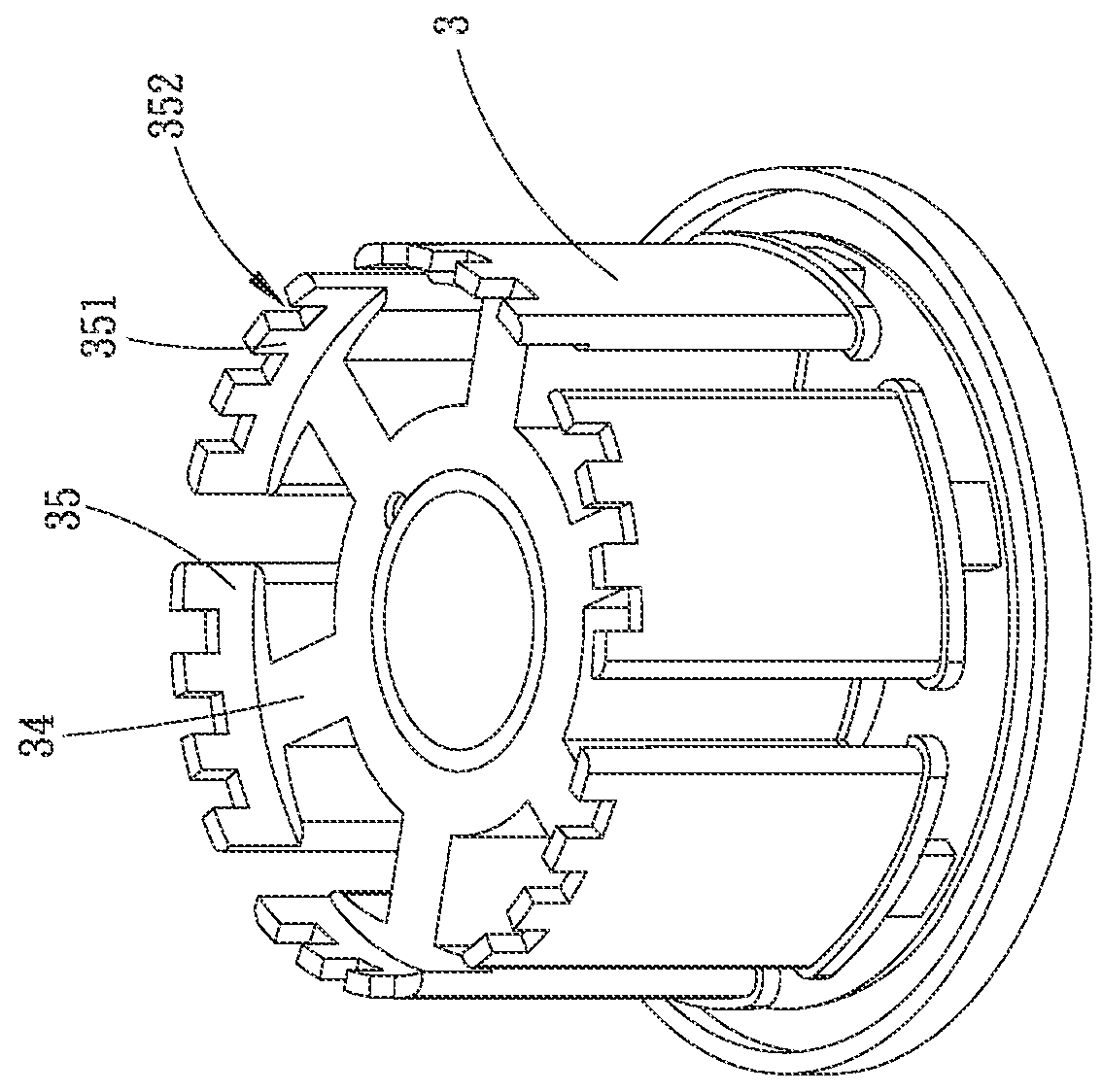
[0024]Please refer to FIG. 3, which is a perspective view of a first embodiment of the stator structure of the present invention. According to the first embodiment, the stator structure of the present invention includes a main body 3 having multiple poles 34. The poles 34 outward extend from the main body 3. Each pole 34 has a free end. The end face of the free end of the pole 34 has an extension section 35 normal to the main body 3. The extension section 35 has multiple protrusion blocks 351. Each two adjacent protrusion blocks 351 define therebetween a recess 352. The protrusion blocks 351 and the recesses 352 are arranged at equal intervals.

[0025]According to the structural design of the present invention, in operation of the fan, the protrusion blocks 351 formed on the extension section 35 serve to increase the total magnetic induction area of the main body 3 to enhance the operation efficiency of the motor. In addition, the protrusion blocks 351 and the recesses 352 are alterna...


PUM


Abstract

A stator structure includes a main body. The main body has multiple poles. The poles outward extend from the main body. Each pole has a free end. An end face of the free end of the pole has an extension section normal to the main body. The extension section has multiple protrusion blocks. Each two adjacent protrusion blocks define therebetween a recess. The stator structure is able to greatly enhance the operation efficiency of the motor and lower manufacturing cost.

Description

BACKGROUND OF THE INVENTION[0001]1. Field of the Invention[0002]The present invention relates generally to a stator structure, which is able to greatly enhance the operation efficiency of the motor and lower the manufacturing cost.[0003]2. Description of the Related Art[0004]In current society, a cooling fan has become a very important part of the modern electronic products ranging from small-size portable electronic device to large-size electronic equipments of transportation tool. In operation, the electronic equipment often generates high heat at the same time to affect the working performance or even lead to shutdown of the electronic equipment. Therefore, the electronic equipment is generally provided with a cooling fan to dissipate the heat and lower the temperature of the electronic equipment so as to keep the electronic equipment stably operating. The reliability and durability of the cooling fan itself are key factors of stable operation of the electronic equipment. All the...

Claims


Application Information

Patent Timeline
Patent Type & Authority Patents(United States)
IPC IPC(8): H02K1/14H02K1/12
CPCH02K1/146H02K1/12
Inventor HO, CHUN-LIANG
Owner ASIA VITAL COMPONENTS SHENZHEN CO LTD
Why Eureka
Try Eureka