Implantable penile prosthesis

a penile prosthesis and expandable technology, applied in the field of implantable penile prosthesis, can solve the problems of potential aneurysm risk, elastic fabric beginning to wear, and weak spots in the elastic sleeve, and achieve the effect of reducing the potential for aneurysm, preventing further expansion of the molded sleeve, and reducing wear risks

Active Publication Date: 2018-06-19
BOSTON SCI SCIMED INC
View PDF18 Cites 2 Cited by
  • Summary
  • Abstract
  • Description
  • Claims
  • Application Information

AI Technical Summary

Benefits of technology

[0012]According to certain examples, sidewalls of the expandable sleeve in a relaxed disposition can comprise fenestrations between longitudinally-extending spokes generally extending in a direction between ends of the sleeve, and lateral ribs generally extending laterally between and connecting the spokes. The ribs may be shaped or linear; if shaped, ribs can be in-elastically extendable laterally and deformed to lengthen and allow the cross-sectional size of the sleeve to expand, e.g., allowing the girth and diameter of the sleeve to increase. A shaped rib that can in-elastically extend laterally may be of a non-linear shape, such as a crooked (cornered), chevron-shaped, curved (e.g., of a waveform such as sinusoidal, U-shaped (having a single curve), S-shaped (having two opposing curves), V-shaped, or any other shape that can be lengthened in-elastically. Optionally, any such shaped rib can also be lengthened elastically after being fully lengthened in-elastically.
[0022]In another aspect the invention relates to a method of improving a performance property of a penile prosthesis adapted to be implanted in a corpus cavernosum. The method includes: providing an implantable penile prosthesis as described herein; and increasing a thickness of a sidewall of the polymeric sleeve, or increasing a dimension of a sidewall structure of the polymeric sleeve, to improve a performance property.

Problems solved by technology

A potential disadvantage of the elastic sleeve is that over time and following numerous expansion cycles, the potential exists for the elastic fabric to begin wearing and creating weak spots in the elastic sleeve, such as at locations of a fold.
When such wear occurs and weak spots are formed, the potential exists for the inner tube to swell and potentially burst at such a weak spot.
This can result in a potential aneurysm where the pressurized inflation fluid is able to escape the inflatable cylinder and to be introduced into the corpus cavernosum.

Method used


Image

  • Implantable penile prosthesis
  • Implantable penile prosthesis
  • Implantable penile prosthesis

Examples


Embodiment Construction

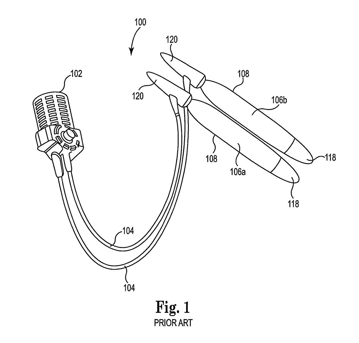
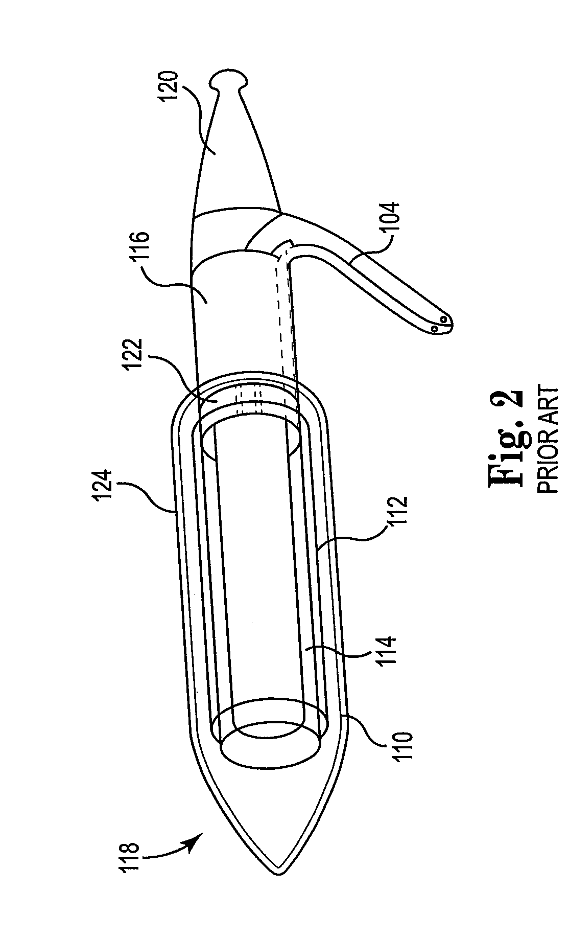
[0041]Various types and sizes of implantable penile prostheses are available for treatment of erectile dysfunction. A typical penile prosthesis includes at least one pair of inflatable cylinders, each of the pair being designed to be implantable in one of the corpora cavernosa. The penile prosthesis further includes a pump external to the cylinder for pressurizing the cylinder. The pump is typically connected to the cylinder through tubing near a proximal end of the cylinder. Each cylinder has a fluid tube connected thereto. A pump, typically disposed in the scrotum or abdomen, is connected to a reservoir, which may be at any of various locations. The cylinders are inflated as fluid is pumped from the reservoir, and are deflated as fluid is transferred back to the reservoir. This inflation and deflation allows the patient to control whether his penis is erect or flaccid. An example of such penile prosthesis is the AMS 700™ inflatable penile prosthesis manufactured by American Medica...


PUM


Abstract

The present application is generally directed to an expandable sleeve component of an implantable penile prosthesis, to a prosthesis containing the sleeve, and to related methods of preparation and use. More specifically, the present application is directed to an implantable penile prosthesis having a cylindrical polymeric (e.g., extruded, molded, etc.) sleeve for controlling cylinder expansion upon placement of the prosthesis within a corpus cavernosum and expansion during use.

Description

PRIORITY CLAIM[0001]The present patent Application claims benefit from International Application No. PCT / US2013 / 062131, filed Sep. 27, 2013, which in turn claims priority under 35 USC § 119(e) from U.S. Provisional Patent Application Ser. No. 61 / 706,468, filed Sep. 27, 2012, entitled “IMPLANTABLE PENILE PROSTHESIS,” both of which are incorporated herein by reference in their entireties.FIELD OF THE INVENTION[0002]The present application is generally directed to an expandable sleeve component of an implantable penile prosthesis, to a prosthesis containing the sleeve, and to related methods of preparation and use. More specifically, the present application is directed to an implantable penile prosthesis having a cylindrical polymeric (e.g., extruded, molded, etc.) sleeve for controlling cylinder expansion upon placement of the prosthesis within a corpus cavernosum and expansion during use.BACKGROUND[0003]Implantation of an implantable penile prosthesis (IPP) is a common surgical proce...

Claims


Application Information

Patent Timeline
Patent Type & Authority Patents(United States)
IPC IPC(8): A61F2/26A61F2/48
CPCA61F2/26A61F2002/484F04C2270/041A61F2230/0069A61F2210/0071A61F2/484
Inventor DARNELL, RYANBERKENES, ROBERT J.RYKHUS, JR., ROBERT L.
Owner BOSTON SCI SCIMED INC
Why Eureka
Try Eureka