Fuel filter assembly

a technology of fuel filter and assembly, which is applied in the direction of filtration separation, machine/engine, separation process, etc., to achieve the effect of reducing costs

Inactive Publication Date: 2001-05-08
DAVCO TECH
View PDF33 Cites 15 Cited by
  • Summary
  • Abstract
  • Description
  • Claims
  • Application Information

AI Technical Summary

Benefits of technology

The present invention provides a fuel filter assembly that provides a constant level of restricted fuel flow through a filter media during the useful life of the filter media by utilizing a minimum amount of filter media to obtain the least possible restricted fuel flow while providing a fuel additive whose addition is proportionally related to the amount of filter media required for the least possible restricted fuel flow. The present invention also provides a means by which to accurately assess the useful life of the filter media and fuel additive so that proper and efficient replacement of the filter media and fuel additive will occur. In addition, the present invention provides a multi-purpose access for removing and / or replacing the fuel additive without the need for disassembling the fuel filter assembly, for providing a means for venting the fuel filter assembly to drain the fuel from the fuel filter assembly, and for providing access to prime the fuel filter assembly directly with fuel. A well is provided in the fuel filter assembly for collecting excess fuel when the fuel filter assembly is vented so that fuel does not escape into the environment or into the engine unfiltered and untreated. Replacement parts for the fuel filter assembly are entirely combustible so that the replacement portions of the fuel filter assembly can be discarded at a minimal expense and concern.

Problems solved by technology

This results in the fuel level resting at a level where there is enough unobstructed filter media to provide the least possible restriction to fuel flow.

Method used


Image

  • Fuel filter assembly
  • Fuel filter assembly
  • Fuel filter assembly

Examples


Embodiment Construction

Referring to the drawings, the present invention will now be described in detail with reference to the preferred embodiment.

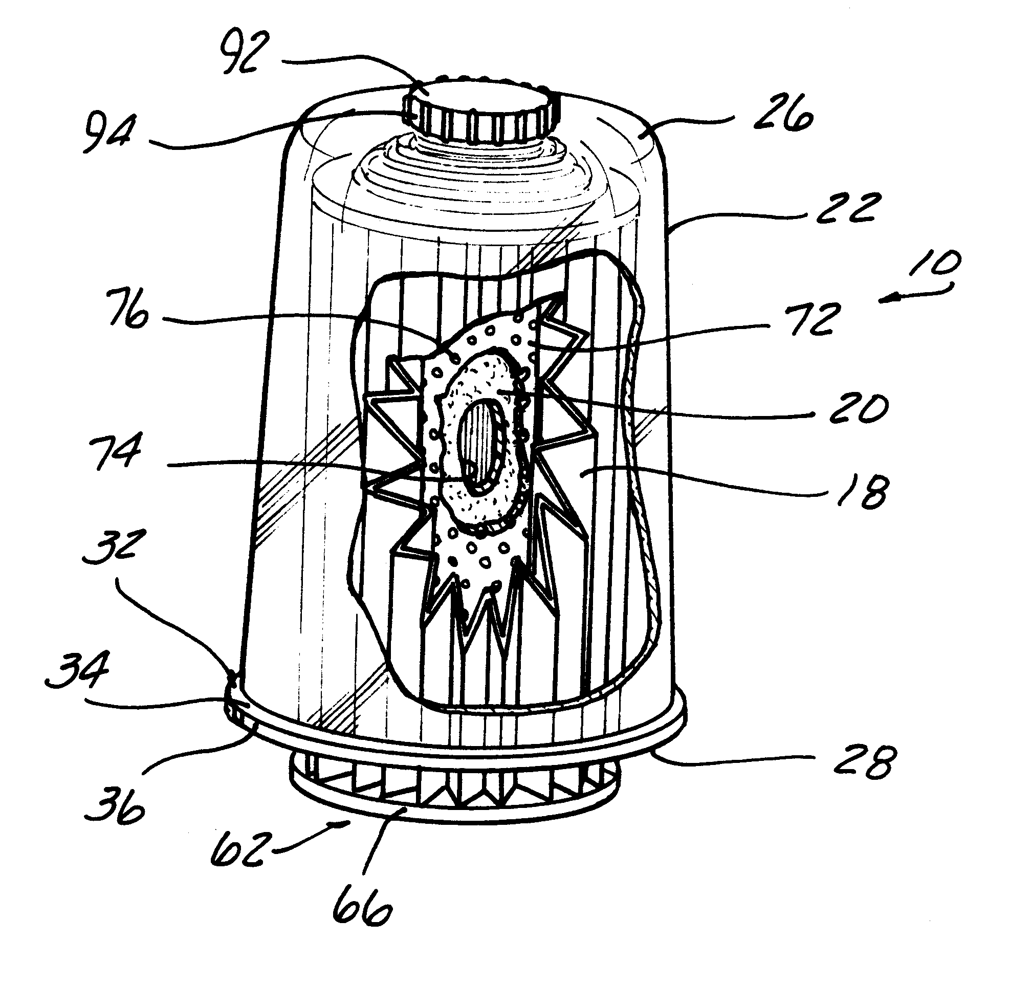
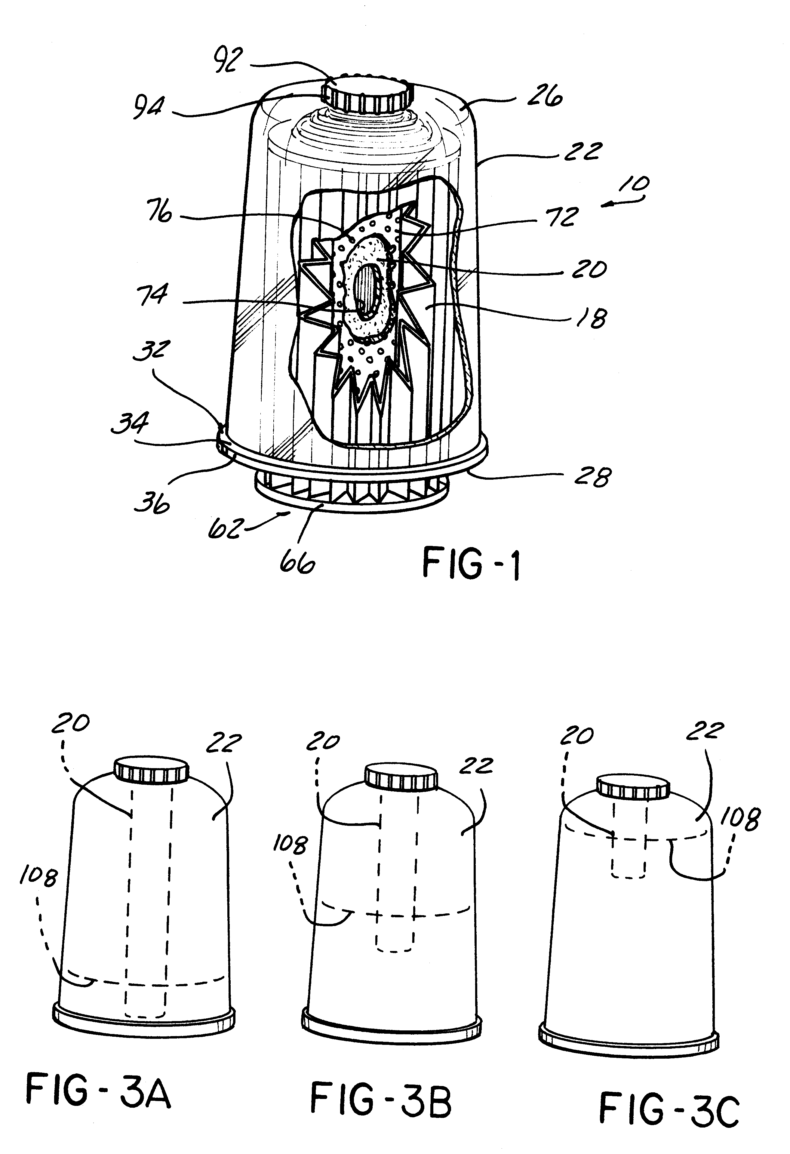
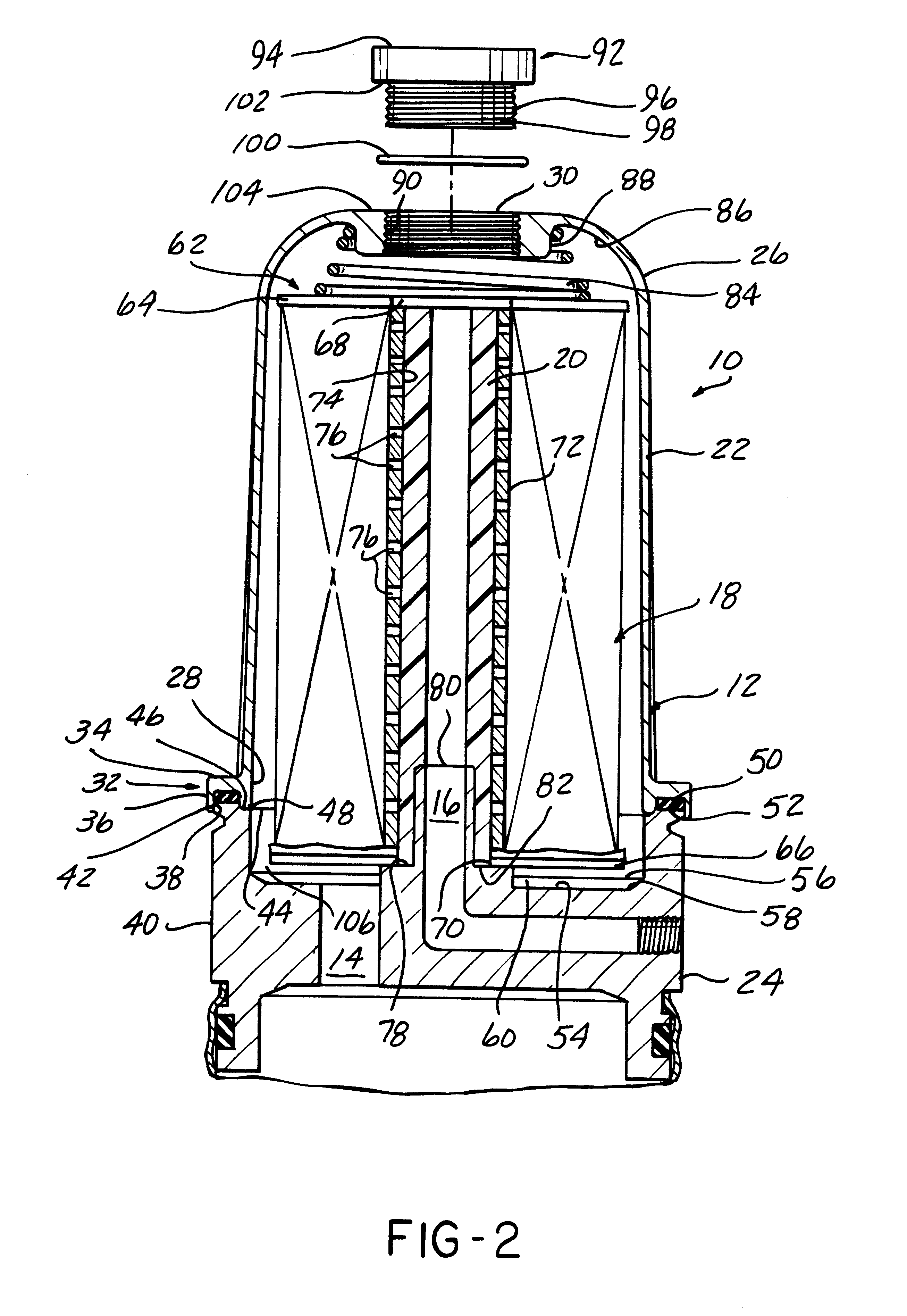
FIGS. 1 and 2 show the fuel filter assembly 10 in its preferred form. The fuel filter assembly 10 is mounted vertically upright and provides a closed housing 12 having a fuel inlet 14 that is in communication with a fuel storage tank (not shown) and a fuel outlet 16 that is in communication with an engine (not shown) of a motor vehicle (not shown). A filter media 18 is housed within the housing 12, and a fuel additive 20 is contained within the filter media 18. The fuel inlet 14 delivers fuel (not shown) into the housing 12 so that the fuel passes through the filter media 18 and contacts the fuel additive 20. The fuel additive 20 is soluble in fuel and dissolves in the fuel. The filtered and treated fuel exits through the fuel outlet 16 and flows to the engine.

To allow for maintenance of the fuel filter assembly 10, a simple means for disassembling and reassemb...


PUM

PropertyMeasurementUnit
surface areaaaaaaaaaaa
hydrophobicaaaaaaaaaa
transparentaaaaaaaaaa

Abstract

A fuel filter assembly that provides a constant level of least restricted fuel flow through the fuel filter assembly during the useful life of the filter media by utilizing the least possible amount of filter media to provide the least possible pressure differential over the filter media while also providing a constant level of fuel additive by exposing an amount proportional to the filter media required for the least possible restricted fuel flow. The fuel filter assembly utilizes a vertically upward housing that houses a filter media and a fuel additive. The fuel level slowly rises in the housing as the filter media becomes obstructed with contaminants and as the fuel additive dissolves over the life of the filter media. The top portion of the housing is made of a transparent material so that the level of fuel may be easily determined, thereby allowing for an accurate and simple assessment of the useful life of the filter media and the fuel additive. The housing also provides a multi-purpose aperture provided in the top of the housing to provide for removal and/or replacement of the fuel additive and venting and priming of the housing. The filter media and fuel additive are entirely fabricated from combustible materials so that both may be easily discarded without cost and environmental concerns.

Description

FIELD OF THE INVENTIONThe present invention relates to fuel filter assemblies and more particularly, to a fuel filter assembly that provides a constant level of restricted fuel flow through the fuel filter assembly during the useful life of the filter media by utilizing a minimum amount of filter media to obtain the least possible restricted fuel flow while providing a fuel additive whose addition is proportionally related to the amount of filter media required for least possible restricted fuel flow.BACKGROUND OF THE INVENTIONIt is well known to utilize fuel filter assemblies to filter fuel for a combustible engine of a motor vehicle. Such fuel filter assemblies typically comprise a sideways or downwardly mounted canister having a paper filter media enclosed in the canister. The fuel enters and fills the canister so that all of the filter media is doused with fuel as the fuel passes through the paper filter media and exits the canister to travel to the engine. Various contaminants ...

Claims


Application Information

Patent Timeline
Patent Type & Authority Patents(United States)
IPC IPC(8): B01D37/00B01D37/02B01D29/15B01D29/13C10L10/00C10L1/10F02M25/00F02M37/22C10L1/16B01D27/10F02M37/24F02M37/32
CPCB01D17/10B01D29/15B01D37/025B01D2201/309C10L1/10C10L1/1691C10L10/00F02M25/00F02M37/24F02M37/32B01D27/10
Inventor DAVIS, LELAND L.
Owner DAVCO TECH
Why Eureka
Try Eureka