
Apparatus, system, and method for detecting cracking within an aftertreatment device

a technology of aftertreatment device and aftertreatment device, which is applied in the direction of resistance/reactance/impedence, separation process, instruments, etc., can solve the problems of aftertreatment device failure, particularly difficult detection of aftertreatment device, and failure of aftertreatment device, so as to achieve the effect of reducing expense and effor

Active Publication Date: 2009-04-30
CUMMINS FILTRATION IP INC
View PDF13 Cites 21 Cited by
  • Summary
  • Abstract
  • Description
  • Claims
  • Application Information

AI Technical Summary

Benefits of technology

[0012]The present invention has been developed in response to the present state of the art, and in particular, in response to the problems and needs in the art that have not yet been fully solved by currently available particulate filter systems. Accordingly, the present invention has been developed to provide an apparatus, system, and method for detecting cracks in a particulate filter that overcome many or all of the above-discussed shortcomings in the art.

Problems solved by technology

The thermal cycles may be intentional, for example during the removal of soot from a particulate filter, or unintentional such as when the engine experiences large changes in the required workload for the engine.
The temperature gradient within the device may cause stresses and over time can cause the aftertreatment device to fail.
A stress related failure within an aftertreatment device, such as a crack in the wall of the aftertreatment device, can be particularly difficult to detect.
There are no direct measurements routinely used in real-time for applications to detect such failures.
Even when an aftertreatment device is being serviced, it is difficult for a service technician to detect such a failure even if the technician has a reason to look for it.
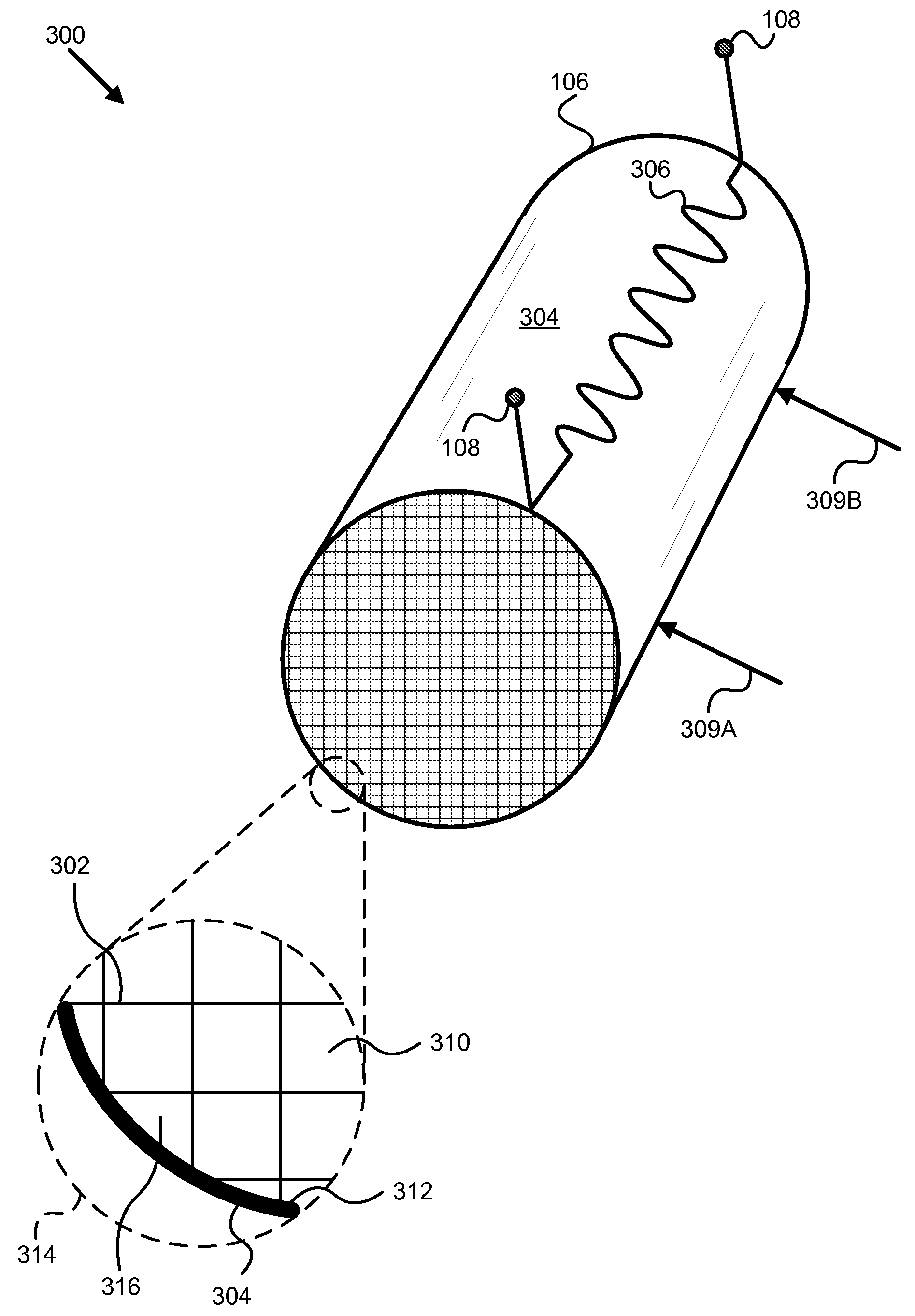
The aftertreatment device typically comprises a core—such as cordierite or silicon carbide—wrapped in a mesh that fixes the core in place, and the whole device is typically covered by a sheet metal and / or stainless steel “can.” A stress failure on a device occurs in the core, typically as radial cracking around the surface of the core, and is not visible to a technician merely handling the device.
Ultrasound detection schemes are problematic because of the intentional porous nature of the aftertreatment devices, and the gaps in the surrounding mesh.
The ultrasound frequency must be so low (causing a low resolution image), and the aftertreatment devices are so poorly configured for ultrasound analysis, that often only the most catastrophic failures can be detected.
However, some aftertreatment devices are no longer design compliant—which can mean regulatory emissions thresholds are not being met—with only a few moderate cracks around the device.
The channels of the device may be packed with soot and / or debris, rendering the inspection difficult or impossible.
The inspection procedure can damage the aftertreatment device, and is time consuming and costly under the best of circumstances.
These limitations in the current technology result the discovery of aftertreatment device failures only when a technician has a specific reason to suspect a failure, only at considerable expense, and often only after a device has failed far beyond a threshold of design compliance.
These limitations also introduce the risks attendant with aftertreatment devices with hidden defects.
Under the current state of technology, there is a significant risk that one of the swapped aftertreatment devices may have a stress failure, penalizing either the customer or the service company according to which device has failed.

Method used


Image

  • Apparatus, system, and method for detecting cracking within an aftertreatment device
  • Apparatus, system, and method for detecting cracking within an aftertreatment device
  • Apparatus, system, and method for detecting cracking within an aftertreatment device

Examples


Embodiment Construction

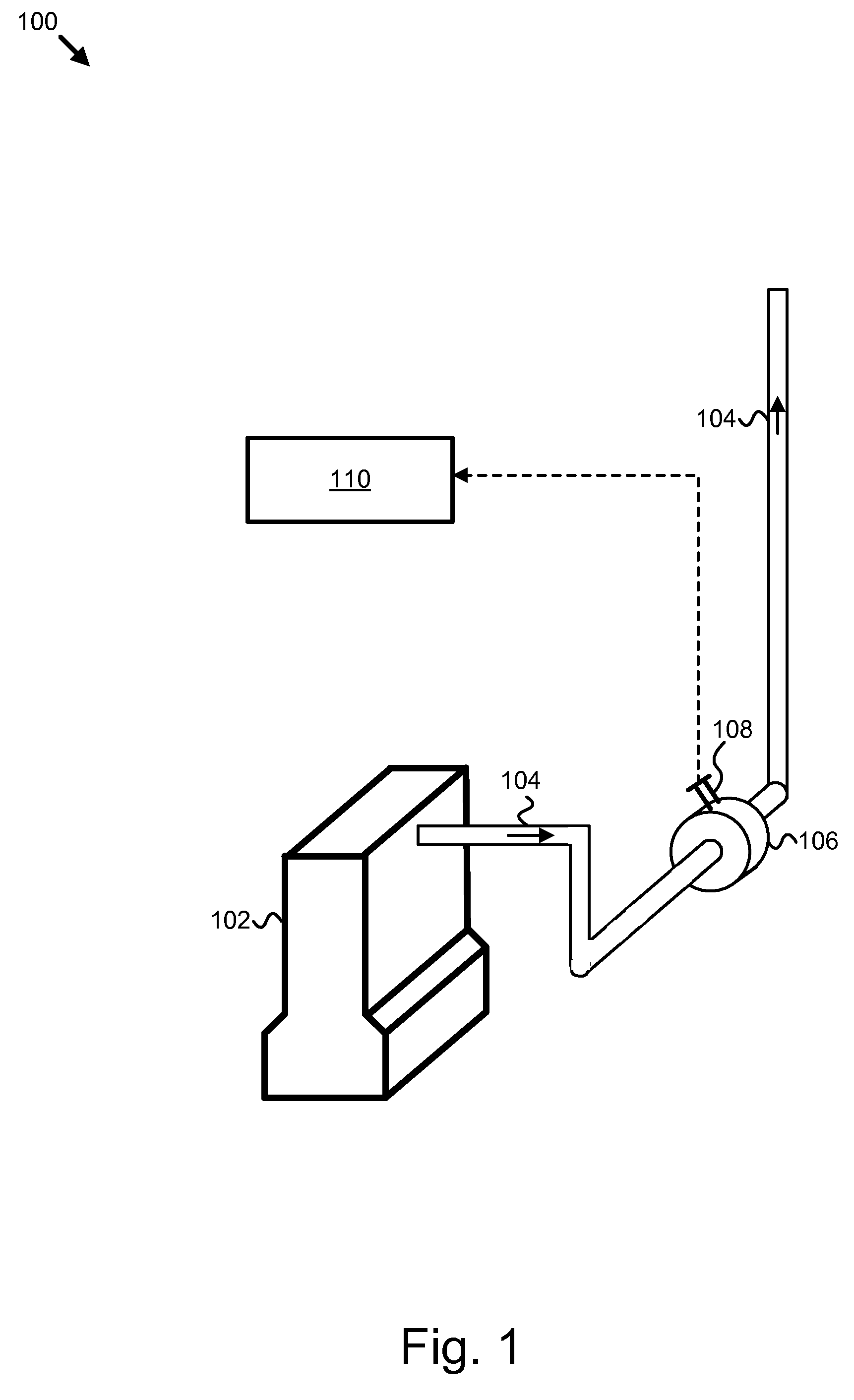
[0032]It will be readily understood that the components of the present invention, as generally described and illustrated in the figures herein, may be arranged and designed in a wide variety of different configurations. Thus, the following more detailed description of the embodiments of the apparatus, system, and method of the present invention, as presented in FIGS. 1 through 9, is not intended to limit the scope of the invention, as claimed, but is merely representative of selected embodiments of the invention.

[0033]Reference throughout this specification to “one embodiment” or “an embodiment” means that a particular feature, structure, or characteristic described in connection with the embodiment is included in at least one embodiment of the present invention. Thus, appearances of the phrases “in one embodiment” or “in an embodiment” in various places throughout this specification are not necessarily all referring to the same embodiment.

[0034]Furthermore, the described features, ...


PUM

PropertyMeasurementUnit
thicknessaaaaaaaaaa
thicknessaaaaaaaaaa
stressaaaaaaaaaa

Abstract

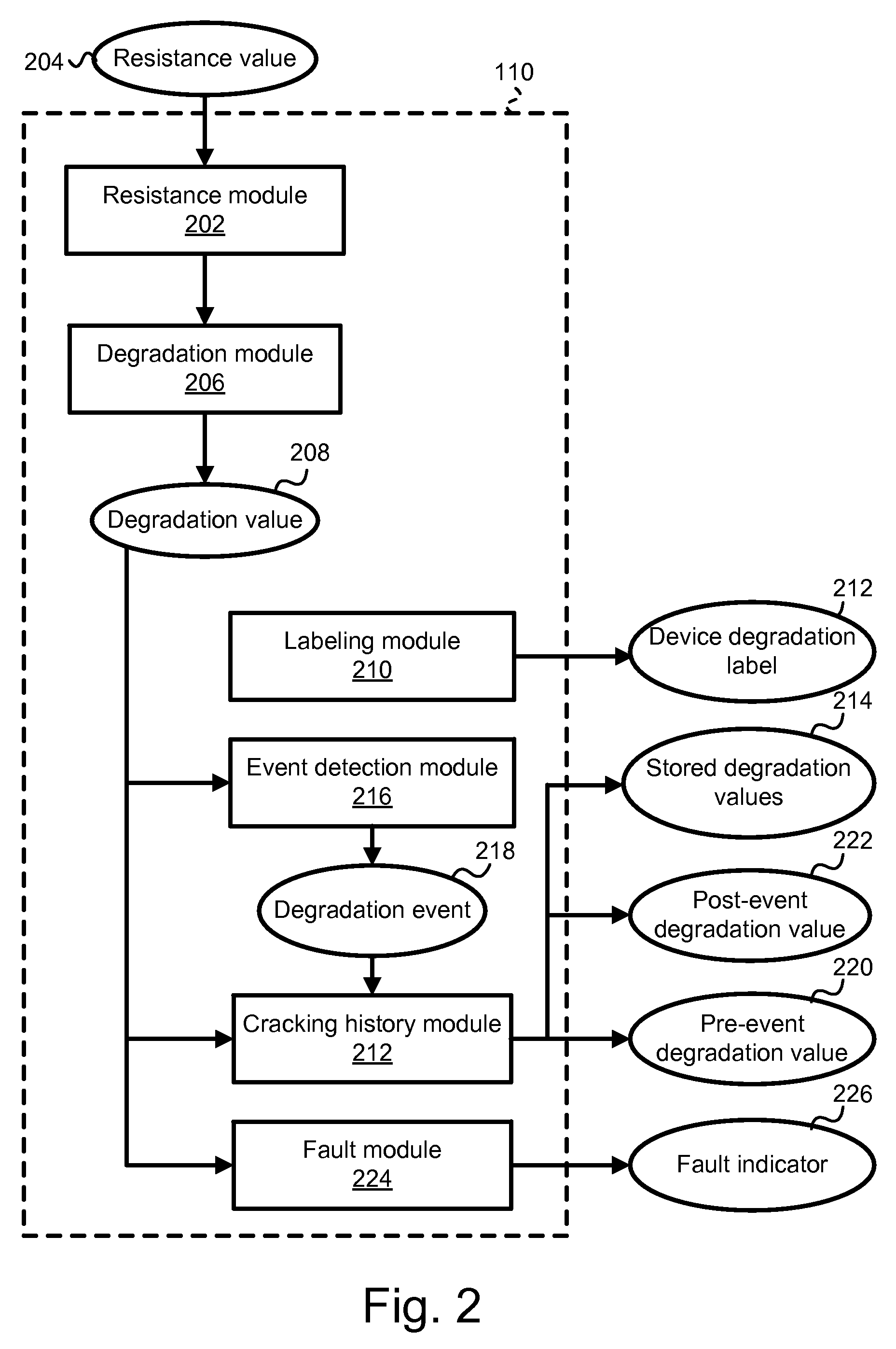
An apparatus, system, and method are disclosed for detecting cracking in a particulate filter. The method may include providing an apparatus comprising an aftertreatment device with a substrate and a substrate surface, a conductive material forming a conduction path bonded to the surface of the substrate surface, and access points configured to allow a resistance measurement of the conduction path. The method may include measuring the resistance of the conduction path, and determining if one or more cracks have occurred on the substrate surface based on the resistance measurement. The method may further include labeling the degradation level of the aftertreatment device based on the indicated amount of cracking, and replacing the aftertreatment device with an equivalent aftertreatment device, based on the degradation level, after a service event.

Description

BACKGROUND OF THE INVENTION[0001]1. Field of the Invention[0002]This invention relates to aftertreatment devices for treating engine exhaust streams, and more particularly relates to detecting physical failures in aftertreatment devices.[0003]2. Description of the Related Art[0004]Emissions regulations for internal combustion engines have changed rapidly in recent years. To meet the new regulations, many engine manufacturers have had to install aftertreatment devices to reduce emissions in the exhaust gases, or to condition the exhaust gases to assist other aftertreatment devices. For example, particulate filters remove soot from the exhaust gases of a diesel engine, and diesel oxidation catalysts are sometimes used to generate temperature in the exhaust gas to assist a particulate filter in oxidizing the soot off of the filter.[0005]Most aftertreatment devices experience thermal cycles during the operations of the engine. The thermal cycles may be intentional, for example during th...

Claims


Application Information

Patent Timeline
Patent Type & Authority Applications(United States)
IPC IPC(8): G01R27/08
CPCB01D2273/18B01D46/0086
Inventor YONUSHONIS, THOMAS M.STAFFORD, RANDALL J.LARA-CURZIO, EDGARSHYAM, AMIT
Owner CUMMINS FILTRATION IP INC
Learn More