Identification icon indicia for plug-in units of a power distribution system

a technology of identification icon and plug-in unit, which is applied in the direction of identification means, electrical apparatus casings/cabinets/drawers, instruments, etc., can solve the problem of incorrect preselection of plug-in units, and achieve the effect of facilitating proper matching of plug-in units

Inactive Publication Date: 2002-03-19
LINEAGE POWER
View PDF5 Cites 7 Cited by
  • Summary
  • Abstract
  • Description
  • Claims
  • Application Information

AI Technical Summary

Benefits of technology

Therefore, icon and background chroma (i.e. color) indicia are provided...

Problems solved by technology

It is not uncommon for an incorrect unit to be plugged in due to time and other pressures causing plug-in unit preselection to be made incorrectl...

Method used


Image

  • Identification icon indicia for plug-in units of a power distribution system
  • Identification icon indicia for plug-in units of a power distribution system
  • Identification icon indicia for plug-in units of a power distribution system

Examples


Embodiment Construction

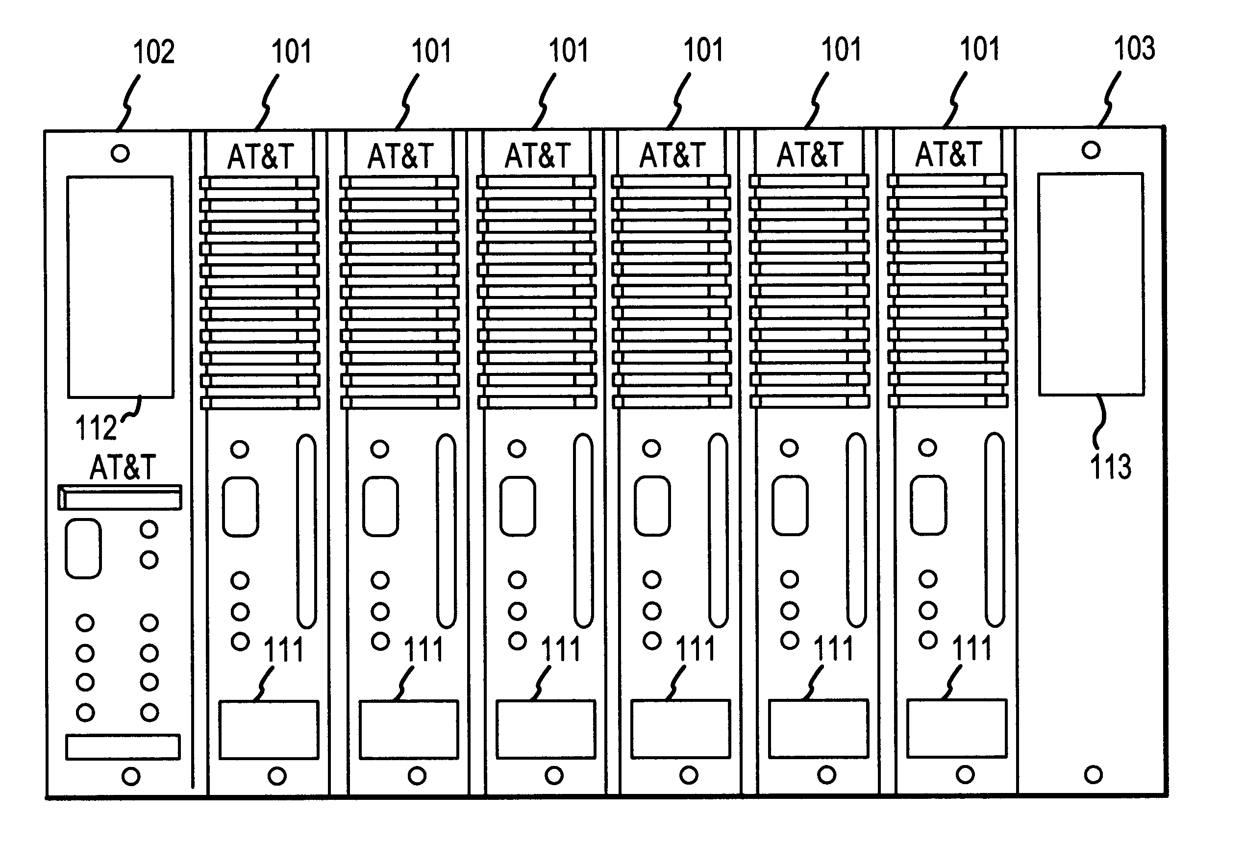
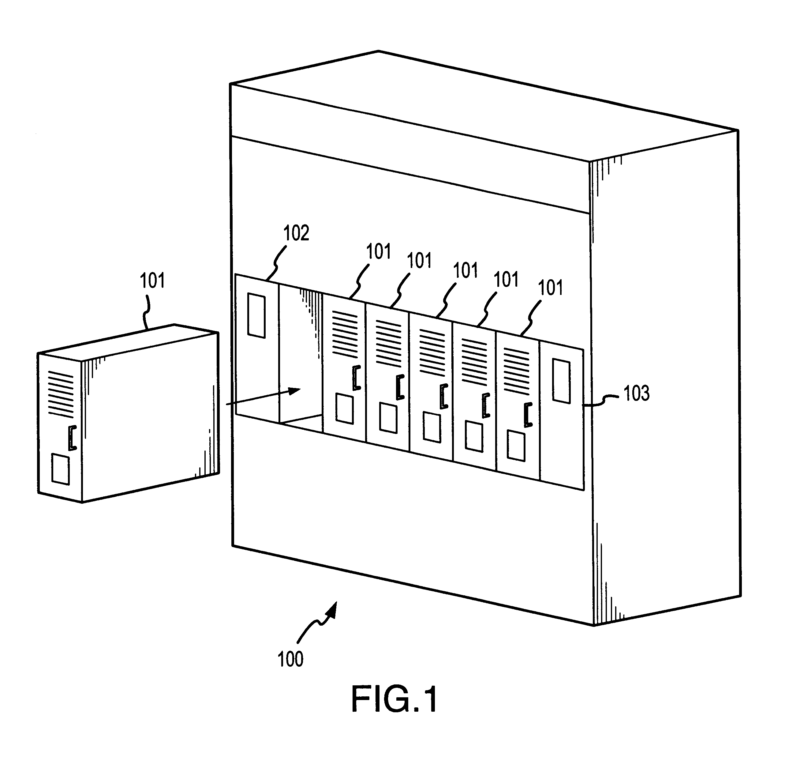
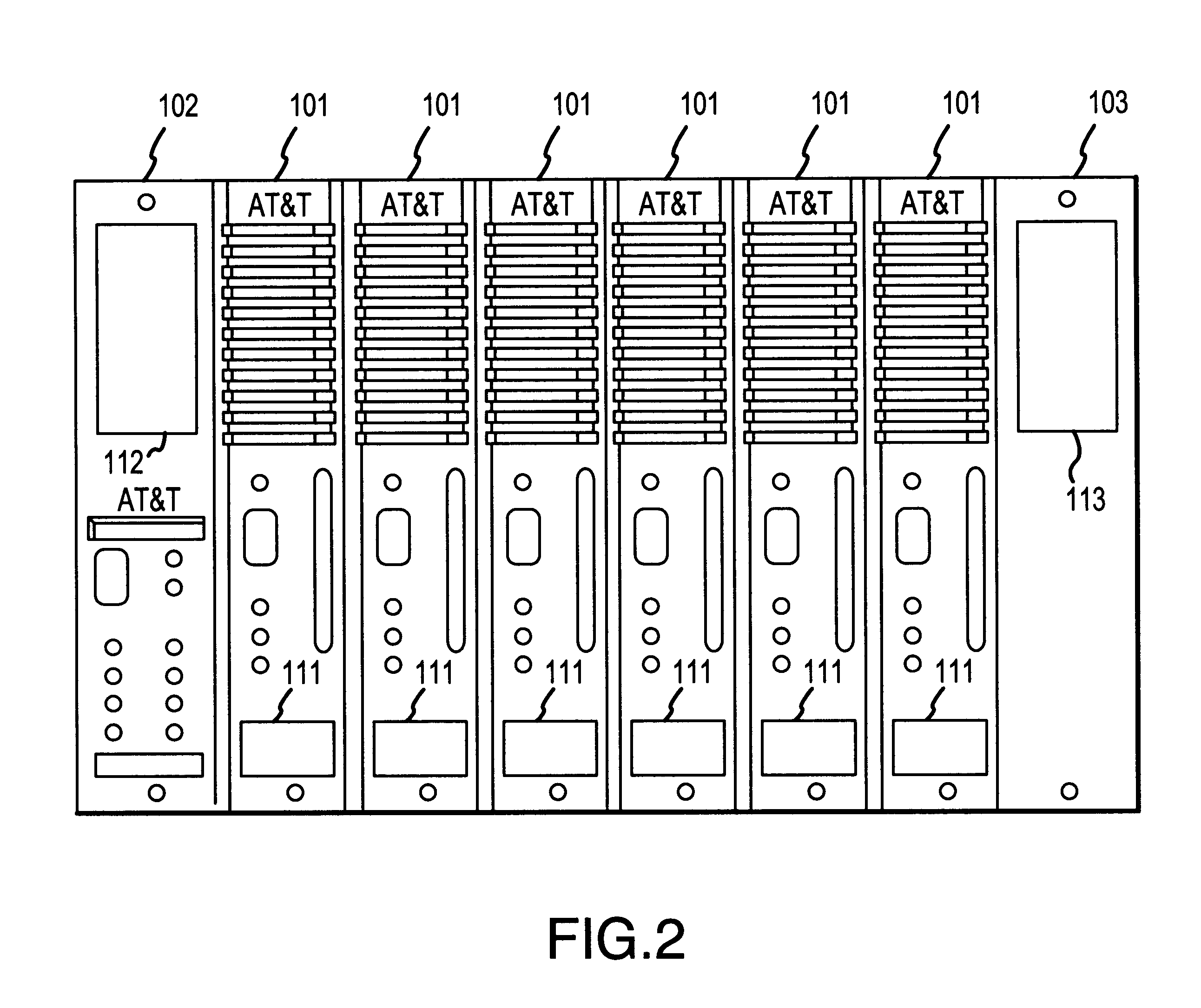
A power processing system chassis or cabinet 100 as shown in the FIG. 1 includes a plurality of power processing units 101, 102, 103 which slide into a shelf of the cabinet and connect to a back plane at the rear of the shelf. Power processing units 102 and 103 at the end of the shelf provide power processing and inter connection to a power source and to equipment to be powered. One of the plug-in power processing units 101 is shown prior to being plugged into the shelf and consequent connection to the backplane. The back plane electrically connects the plug-in units 101 into the electrical system between an input power processing unit and an output power processing unit 103, whereby the plug-in power processing units 101 are operative to provide processing of power between the input power processing unit 102 and the output power processing unit 103. As such, the plug-in power processing units 101 must be compatible with the electrical specifications of the power processing units 10...


PUM


Abstract

Icon indicia are provided on input, output and plug-in power processing units to permit proper matching of plug-in units with each other and with the input and output power processing units in a power distribution system. The indicia are in a co-ordinated matrix format with input icons on a designated chroma background to identify input voltages and output icons on a second designated chroma background to identify output voltages. Icons and background chroma on the plug-in power processing units are coordinated with related icons and background chroma at the same matrix position on other plug-in units and/or the input and output units to assure the compatibility of all the units. A craftsman inserting a plug-in unit onto a shelf of the power chassis need merely compare the unit's icon and chroma background indicia with the input, output, or other unit's icons and associated chroma background indicia to be assured of inserting the correct plug-in unit into the particular shelf.

Description

FIELD OF THE INVENTIONThis invention relates to a power distribution system having a plurality of differing plug-in units for processing power and in particular to icon indicia attached to the plug-in units to facilitate insertion into plug-in stations included in a support chassis connected to a back plane of the power distribution system.BACKGROUND OF THE INVENTIONPower distribution systems normally can accommodate a variety of plug-in units which plug into various back planes and enable the distribution of various voltage and current levels of power. Given a particular power distribution scheme, the plug-in power units used must function in harmony with one another. This means that they must be properly selected for addition to the backplane. These selections are normally made by a crafts person who is familiar with the requirements of the plug-in units. It is not uncommon for an incorrect unit to be plugged in due to time and other pressures causing plug-in unit preselection to ...

Claims


Application Information

Patent Timeline
IPC IPC(8): G09F3/02H02B11/10H02B11/00H02M7/00H05K5/02
CPCG09F3/02H02B11/10H02M7/003H05K5/0252H02B1/00
Inventor ALDEN, TOR ANDREWFONTANA, EDWARD CLARKSOMDAHL, SONJA K.
Owner LINEAGE POWER
Why Eureka
Try Eureka