
Display panel with network communication function

a display panel and network communication technology, applied in the field of display technology, can solve the problems of consumer or patient only obtaining related information, wrong information being obtained by staff of the shop or hospital, and reducing the size of the display panel housing, saving computer installation costs, and enhancing the applicability of the produ

Inactive Publication Date: 2012-07-05
ADLINK TECH INC
View PDF2 Cites 3 Cited by
  • Summary
  • Abstract
  • Description
  • Claims
  • Application Information

AI Technical Summary

Benefits of technology

[0011]Further, the circuit board comprises a power processing unit for receiving and processing power supply to provide the circuit board and the display module with the necessary working power, a computing unit electrically connected with the power processing unit for processing a network signal into a video signal and a connection module electrically connected with the computing unit for receiving an external network signal and running programmable digital signal transmission. By means of the computing unit and the connection module, the circuit board enables a network signal to be directly displayed on the display module without through a computer, saving much computer installation cost and allowing for local and remote applications
[0012]Further, the computing unit of the circuit board has an embedded system therein. The embedded system in the computing unit allows the user to modify the firmware, enhancing the applicability of the product.

Problems solved by technology

Thus, a consumer or patient can only obtain related information (about disease, subscription, consumed amount, order sheet, etc.) from the staff of the shop or hospital.
In case of a mistake of the staff, a consumer or patient may obtain wrong information.
This way of management is inconvenient and wastes time.
The display screen and the computer require much installation space and may hinder people to walk or to deliver goods.
Further, the installation of a computer and a display screen for public may be not workable due to limited shop space.

Method used


Image

  • Display panel with network communication function
  • Display panel with network communication function
  • Display panel with network communication function

Examples


Embodiment Construction

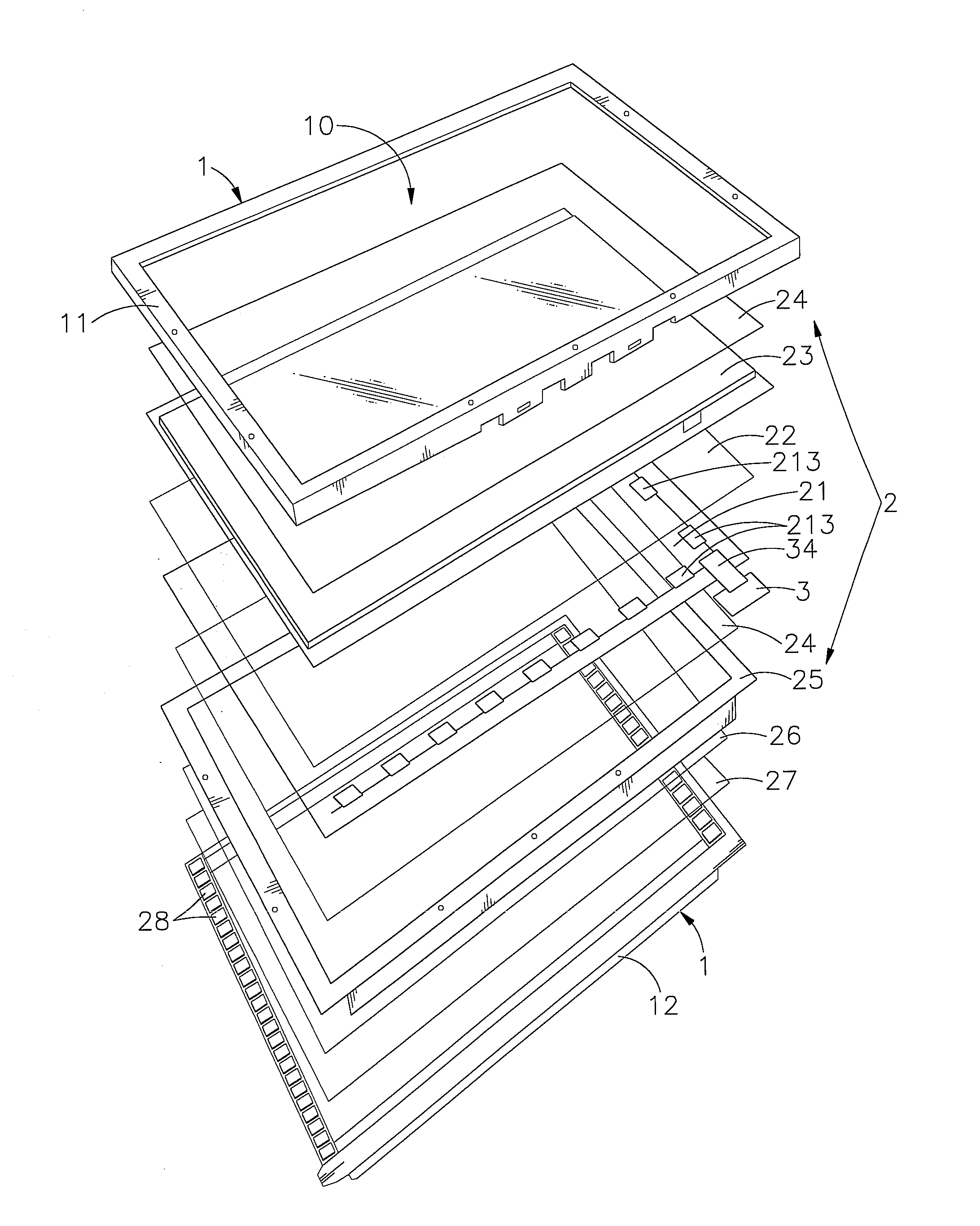
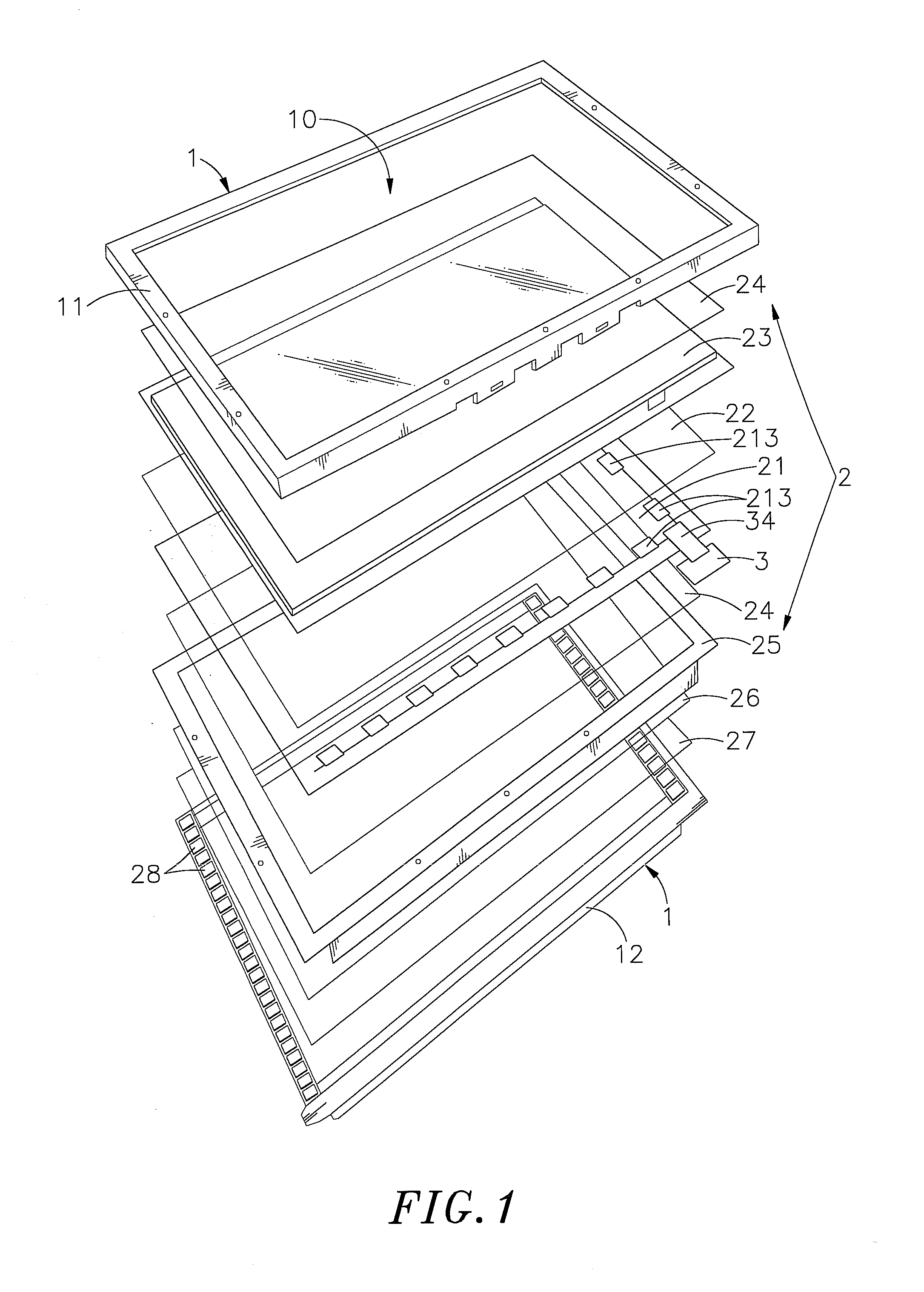
[0017]Referring to FIGS. 1˜3, a display panel with network communication function in accordance with the present invention is shown comprising a housing 1 and a display module 2 and a circuit board 3 accommodated in the housing 1.

[0018]The housing 1 comprises at least one front frame shell 11 and a backlight module 12, defining therein an accommodation chamber 10.

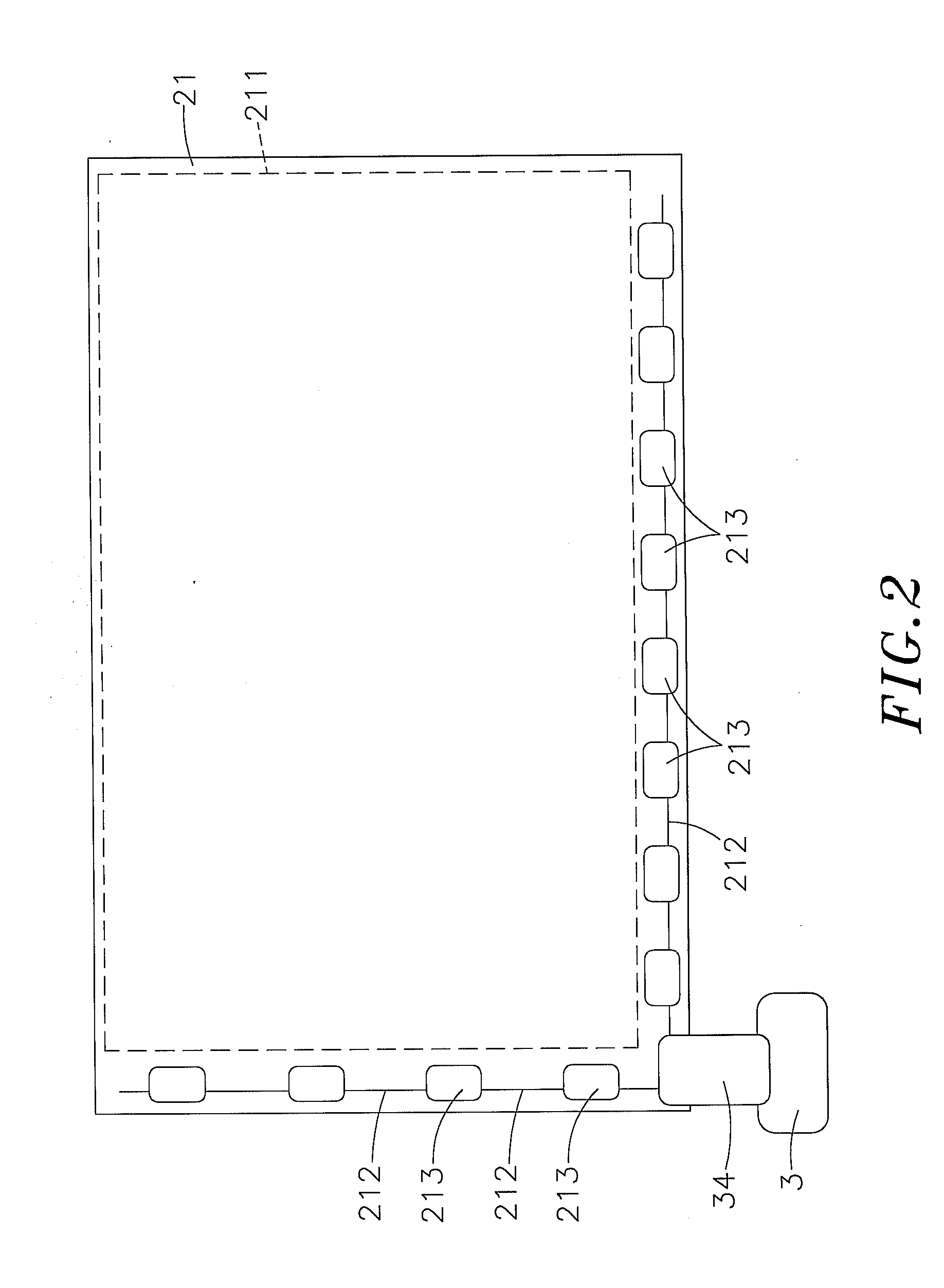
[0019]The display module 2 is mounted in the accommodation chamber 10 inside the housing 1, comprising a glass substrate 21, a liquid crystal layer 22, a color filter 23, two polarizers 24, a mold frame 25, a diffusing sheet 26, a light guiding plate 27 and a lamp unit 28. The glass substrate 21 comprises a display zone 211, an electric circuit 212 arranged at the border area around the display zone 211 and display driver IC chips 213 arranged at the border area around the display zone 211 and electrically connected with the electric circuit 212. The liquid crystal layer 22, the color filter 23 and one polarizer 24 are prop...


PUM


Abstract

A display panel includes a display module accommodated in a housing and comprising an electric circuit mounted on the border the glass substrate thereof beyond the display zone and display driver IC chips electrically connected with the electric circuit, and a circuit board mounted in the housing at one side adjacent to the display driver IC chips and comprising a power processing unit for receiving and processing power supply to provide the circuit board and the display module with the necessary working power, a computing unit carrying therein an embedded system and electrically connected with the power processing unit for processing a network signal into a video signal and a connection module electrically connected with the computing unit for receiving an external network signal and running programmable digital signal transmission.

Description

BACKGROUND OF THE INVENTION[0001]1. Field of the Invention[0002]The present invention relates to display technology and more particularly, to a display panel with network communication function in which the display driver IC chips are arranged on the border area of the glass substrate thereof beyond the display zone, and the circuit board which consists of a power processing unit, a computing unit and a connection module is mounted in the housing at one side of the display panel and adjacent to the display driver IC chips for processing a network signal into a video signal for display. Thus, the display panel has a small size characteristic and provides a network communication function.[0003]2. Description of the Related Art[0004]Following fast development of computer technology, computer has become a requisite tool in our daily living for word processing, data management, design and graphing. A computer system can be used at home for playing audio and video, searching data, making ...

Claims


Application Information

Patent Timeline
IPC IPC(8): G09G5/00
CPCG09G2300/0408G09G3/36
Inventor WANG, CHUN-HSIAO
Owner ADLINK TECH INC
Learn More