Bonus Sieves and Tailings Return for an Articulated Agricultural Harvesting Combine

a combine and bonus sieve technology, applied in the field of articulated combine design, can solve the problems of low cleaning system capacity of the machine, ineffectiveness, and literally inability to raise the sieve high, so as to increase the relative area of the cleaning sieve and increase the effect of mog

Active Publication Date: 2018-02-01
TRIBINE IND
View PDF2 Cites 4 Cited by
  • Summary
  • Abstract
  • Description
  • Claims
  • Application Information

AI Technical Summary

Benefits of technology

[0013]The return of the tailings material via the dual return elevators to the front of the bonus sections of the sieve component, and introduced in such a manner as to have a portion of the air from the bonus fans being used to remove lighter MOG from the material stream such that it does not fall onto the surface of the sieve(s). The tailings material could be discharged into the airflow such that such tailings are splayed out into the air stream for a particulate material flow and are thusly particulately separated such that the air can act upon each particle of grain or MOG independently. The splaying of the tailings material could be assisted by velocity imparted by centrifugal force from the return elevator assembly and centrifugal force.
[0014]The location of the bonus sieves (not necessarily) adjacent to (directly beside while below) the separation area (commonly “separation grates”) of a rotary separator so as to significantly increase the relative area of cleaning sieve in the section of the separator where increased MOG versus grain ratio can be expected, and as such prevent the unfortunate introduction of excess MOG onto the stratified flow in existence on the main sieves in this rearward section of the cleaning system.

Problems solved by technology

This routinely results in the sieves being located between both and / or one of the two sets of tires typical to these machines—large front tires and smaller rear steering tires.
All of this describes why the width of sieves in a typical combine often are reduced to a width that is much less than adequate for the given capacity of a high horsepower modern combine resulting in lower than desired cleaning system capacity of the machine.
It is literally not feasible to raise the sieves high enough to accommodate the axle oscillation if one desires to make the sieves wider near the rear of the machine.
Therefore, it is nearly mandated that if a manufacturer wishes to add addition sieve area, he cannot do it by adding sieve width, which is quite effective, but instead must choose to keep the sieves the same width and just make them longer, which is much less effective.
The crux of this issue is explained as follows: if the rotor is running very near its maximum capacity to thresh and separate the volume of material the feeder is providing, then the rotor cannot effectively address separating at the increased rate that recycling tailings would require.
With an increased burden caused by tailings recycle, the rotor necessarily is beyond its maximum capacity and the percentage of grain recovered diminishes.

Method used


Image

  • Bonus Sieves and Tailings Return for an Articulated Agricultural Harvesting Combine
  • Bonus Sieves and Tailings Return for an Articulated Agricultural Harvesting Combine
  • Bonus Sieves and Tailings Return for an Articulated Agricultural Harvesting Combine

Examples


Embodiment Construction

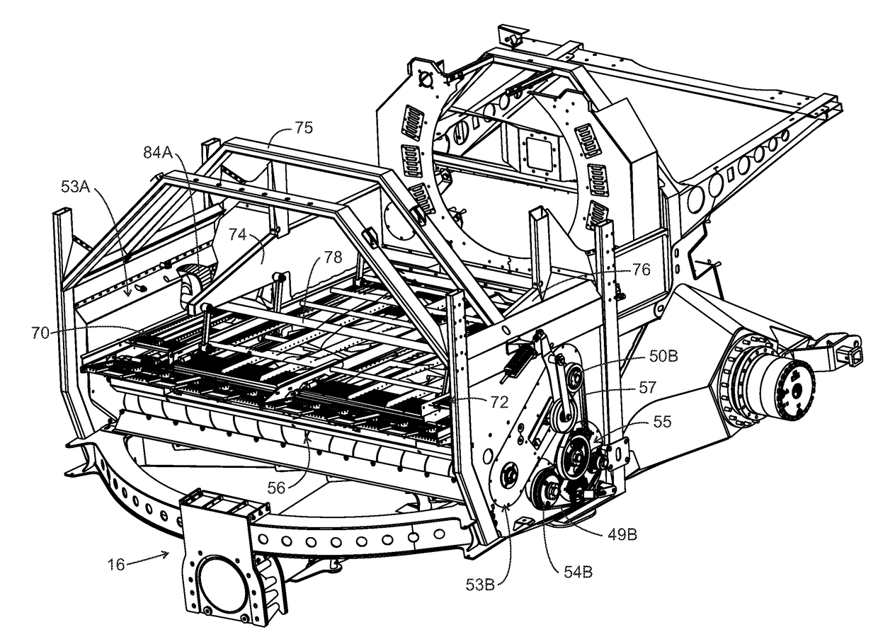
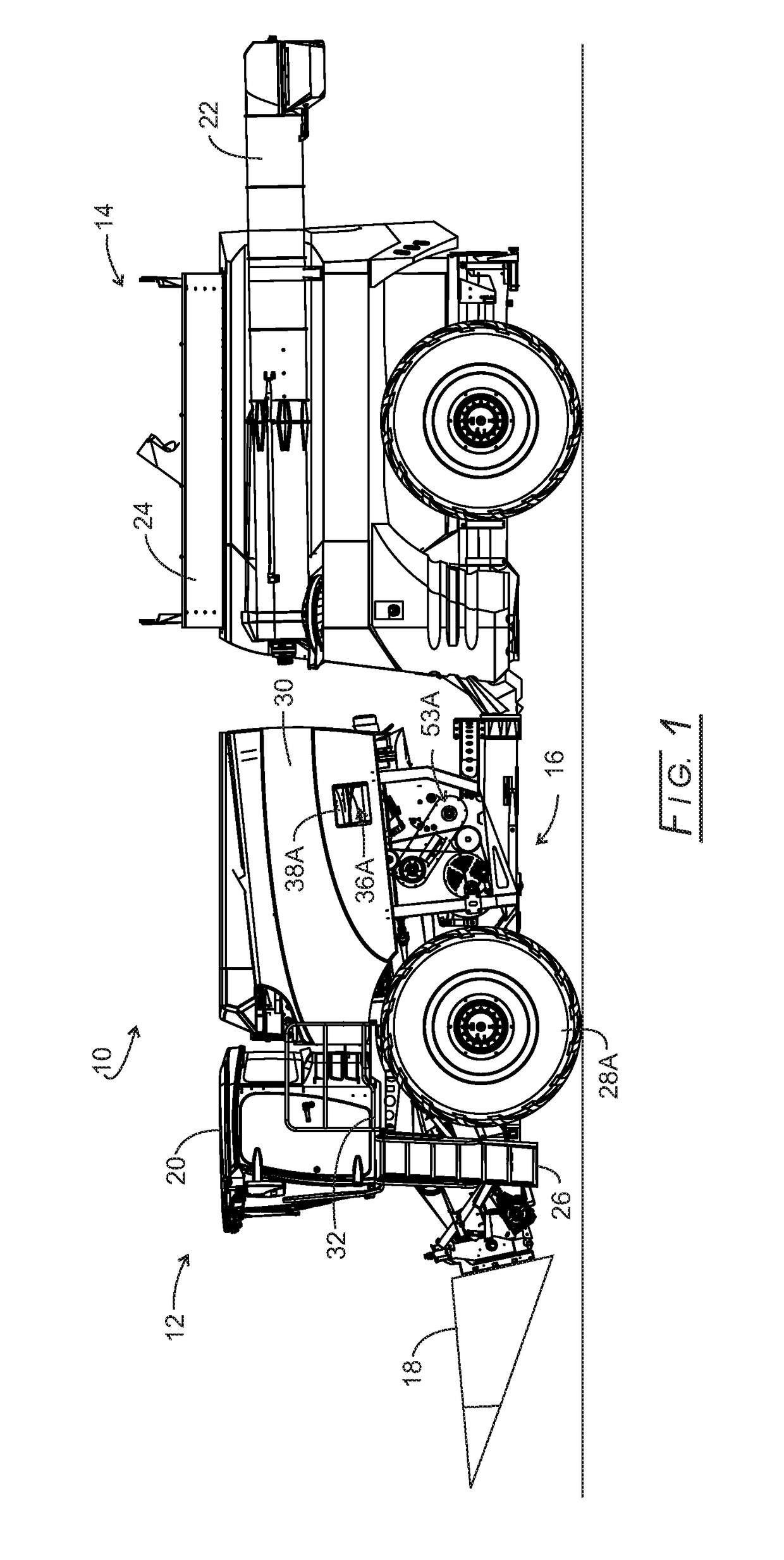
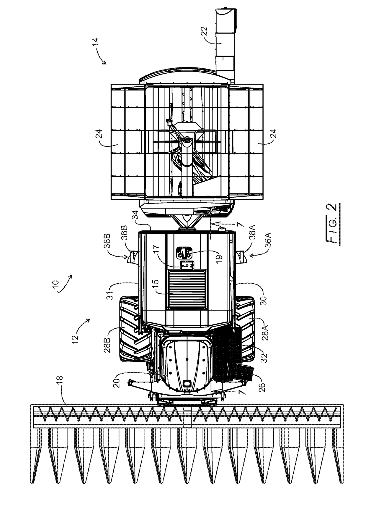
[0029]First and foremost, the articulation architecture of the disclosed harvesting combine permits the power processing (front) unit (PPU) to contain much wider sieves starting at the front of the machine, because the separator frames are wider inasmuch as no rear steering tires / wheels are necessary. This articulation architecture also allows the wider sieves to remain lower in the separator and still be below the threshing rotor. And equally as fortuitous for the sieve area is that, since there is no oscillating rear axle within the area of the separator, the sieves can be configured to be much wider once they progress rearward of the large front tires.

[0030]Digging into the science of sieve operation, the sieves are asked to accept the grain as well as the Material Other than Grain (MOG) that is expelled by the rotor through the concaves and grates that are located directly above the sieves. The ability of the oscillating sieves and the air being pushed up through the sieves to s...


PUM


Abstract

Disclosed is an articulated harvesting combine of a forward power processing unit (PPU) having a forward set of wheel assemblies and a rear grain cart connected by an articulating joint assembly. Bonus sieves assemblies are located in the outer rear of the PPU for accepting grain from concaves and grates assemblies located forward of the bonus sieves assemblies. The bonus sieves assemblies accept tailings from the concaves and grates assemblies for additional separation of grain from material other than grain (MOG). New and separate airflow is provided for the bonus sieves. The bonus sieves tailings are returned to the bonus sieves for rethreshing, optionally after being particulated and air separation performed.

Description

CROSS-REFERENCE TO RELATED APPLICATIONS[0001]This application claims benefit of provisional application 62 / 369,307 filed Aug. 1, 2016; is cross-referenced to application Ser. No. 14 / 946,827 filed Nov. 20, 2015; Ser. No. 14 / 946,842 filed Nov. 20, 2015; Ser. No. 14 / 967,691 filed Dec. 14, 2015; 62 / 235,618 filed Jul. 6, 2016; Ser. No. 15 / 623,619 filed Jun. 15, 2017; and Ser. No. 15 / 642,799 filed Jul. 6, 2017.STATEMENT REGARDING FEDERALLY SPONSORED RESEARCH AND DEVELOPMENT[0002]Not applicable.BACKGROUND OF THE INVENTION[0003]The present disclosure relates to harvesting articulated (jointed) combines and more particularly to an articulated combine design that permits additional sieve capacity concomitant with tailings return thereto.[0004]Typical to the architecture of traditional combines are cleaning sieves that are located to the rear of and beneath the threshing mechanisms of the combine harvester. This routinely results in the sieves being located between both and / or one of the two s...

Claims


Application Information

Patent Timeline
Patent Type & Authority Applications(United States)
IPC IPC(8): A01F12/44A01F12/46
CPCA01F12/446A01F12/46A01F12/444A01F12/52
Inventor MATOUSEK, ROBERT A.
Owner TRIBINE IND
Why Eureka
Try Eureka