Eureka AIR delivers breakthrough ideas for toughest innovation challenges, trusted by R&D personnel around the world.

Leak resistant battery cover

a battery cover and leak-proof technology, applied in the direction of non-aqueous electrolyte accumulator electrodes, cell components, electrical equipment, etc., can solve the problems of large chamber configuration, significant threat to person and property, and battery leakage,

Inactive Publication Date: 2002-11-05
DOUGLAS BATTERY MFG
View PDF27 Cites 13 Cited by
  • Summary
  • Abstract
  • Description
  • Claims
  • Application Information

AI Technical Summary

Benefits of technology

The present invention is directed to a leak resistant battery cover for storage batteries. The battery cover provides a labyrinth of passages providing a path from each cell vent to the atmospheric vent. The labyrinth is configured to provide a portion of each path above a level in which the electrolyte in the respective cells attains when the battery is tipped on any one of its sides or rotated ninety (90) degrees from an upright position. The labyrinth configuration prevents electrolyte from reaching the atmospheric vent and spilling out of the battery.
The passages of the labyrinth may include portions extending horizontally from a passage wall towards the center of the passage. These horizontally extending passages are generally perpendicular to the passage wall or angled in a manner obstructing the flow of electrolyte toward the atmospheric vent. Preferably, the horizontally extending passages alternate from opposing sides of the passage. The labyrinth configuration of the current invention provides improved leak protection over the above discussed prior art when the battery is tipped to one side. Additionally, the substantially convoluted passages provide inverted leak resistance.
The convoluted passages in conjunction with the partitions operate to form an air-lock between the cell vent and the atmospheric vent. By proving such a convoluted path for air to travel, an air-lock is formed in the passages. When air is prevented from entering the battery, additional electrolyte is prevented from leaving each cell, entering the labyrinth and ultimately leaking through the atmospheric vent.
The passages of the labyrinth may also include portions extending vertically from a passage floor or ceiling. The vertically extending passages provide enhanced leak protection when the battery is inverted. Preferably, the vertically extending partitions alternate from the floor and ceiling and the portions extending from the ceiling are substantially longer than the partitions extending from the floor in order to provide a greater electrolyte barrier when inverted. The vertically extending partitions aid in forming an air-lock and preventing air from entering the cells.
Still another aspect of the current invention is to provide the passages of the labyrinth with a plurality of vertically extending partitions extending into the passages to provide resistance to the flow of liquid towards the atmospheric vent. The vertically extending partitions aid in restricting electrolyte flow in the passages and in providing an airlock between the cells and the atmospheric vent when the battery is inverted. The vertically extending partitions may extend from either an upper or lower portion of the passages. Preferably, the upper and lower vertically extending partitions alternate along the passage. The vertically extending partitions extending from the upper portion of the passage extend below a level in which the vertically extending partitions extending from the lower portion extend. The vertically extending partitions provide an obstructed path along the passage.
Still another aspect of the current invention is to provide the common passage of the labyrinth with an entrance, wherein the entrance includes a vertically extending partition adapted to provide resistance to the flow of liquid towards the atmospheric vent. The vertically extending partition at the entrance further aids in providing an airlock between the cells and the atmospheric vent when the battery is inverted.

Problems solved by technology

Although these batteries prevent electrolyte loss during normal operation, the battery will leak, and in many cases pour, electrolyte from the atmospheric vents when the battery is tipped to one side, inverted or agitated.
A significant threat to person and property arises when electrolyte leaks from a battery.
Furthermore, the large chamber configuration provides very limited protection against vibration or agitation when tipped to one side.
The Hennen patent does not disclose a chamberless cover design or provide substantial leak protection over extended periods of time.
The large chambers and passage configuration in Elehew et al. allows substantial amounts of electrolyte to spill into the battery cover; thus, increasing the likelihood of electrolyte being spilled into the venting area and ultimately leaking outside the battery systems.
Having substantial amounts of electrolyte in the cover and limited flow restriction substantially increases the likelihood that electrolyte will spill if the battery is vibrated or agitated after arriving at an equilibrium in a non-upright position.
However, each cover is designed to allow a significant amount of electrolyte to flow into the respective cover and provides no protection against electrolyte leakage when the battery is inverted and very limited protection when vibrated or agitated.
Although the German patent attempts to address inverted leak protection, allowing such substantial amounts of electrolyte to flow out of the cells and into the cover substantially increase the risk of electrolyte leaking outside of the battery system.
Aside from the above arrangements, far more complex arrangements are known which are used on aircraft batteries and the like which not only deal with the problem of electrolyte flowing from the cell when tipped to any one of its sides, but also maintains the battery in operation when completely inverted.
These designs are not cost effective for the majority of battery applications.

Method used


Image

  • Leak resistant battery cover
  • Leak resistant battery cover
  • Leak resistant battery cover

Examples


first embodiment

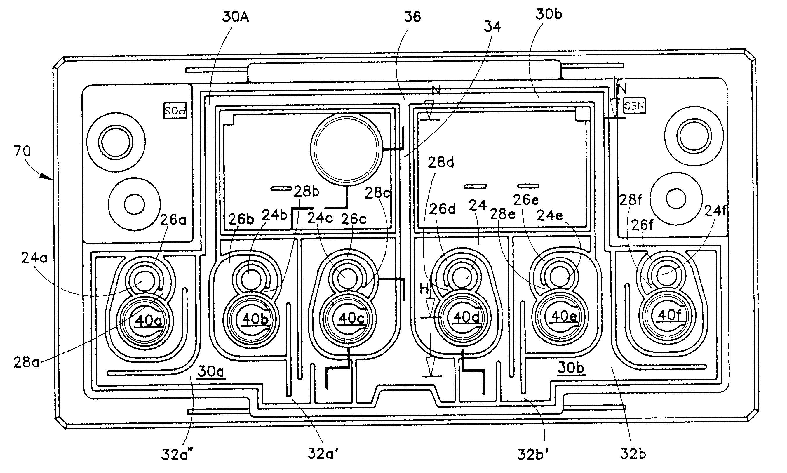
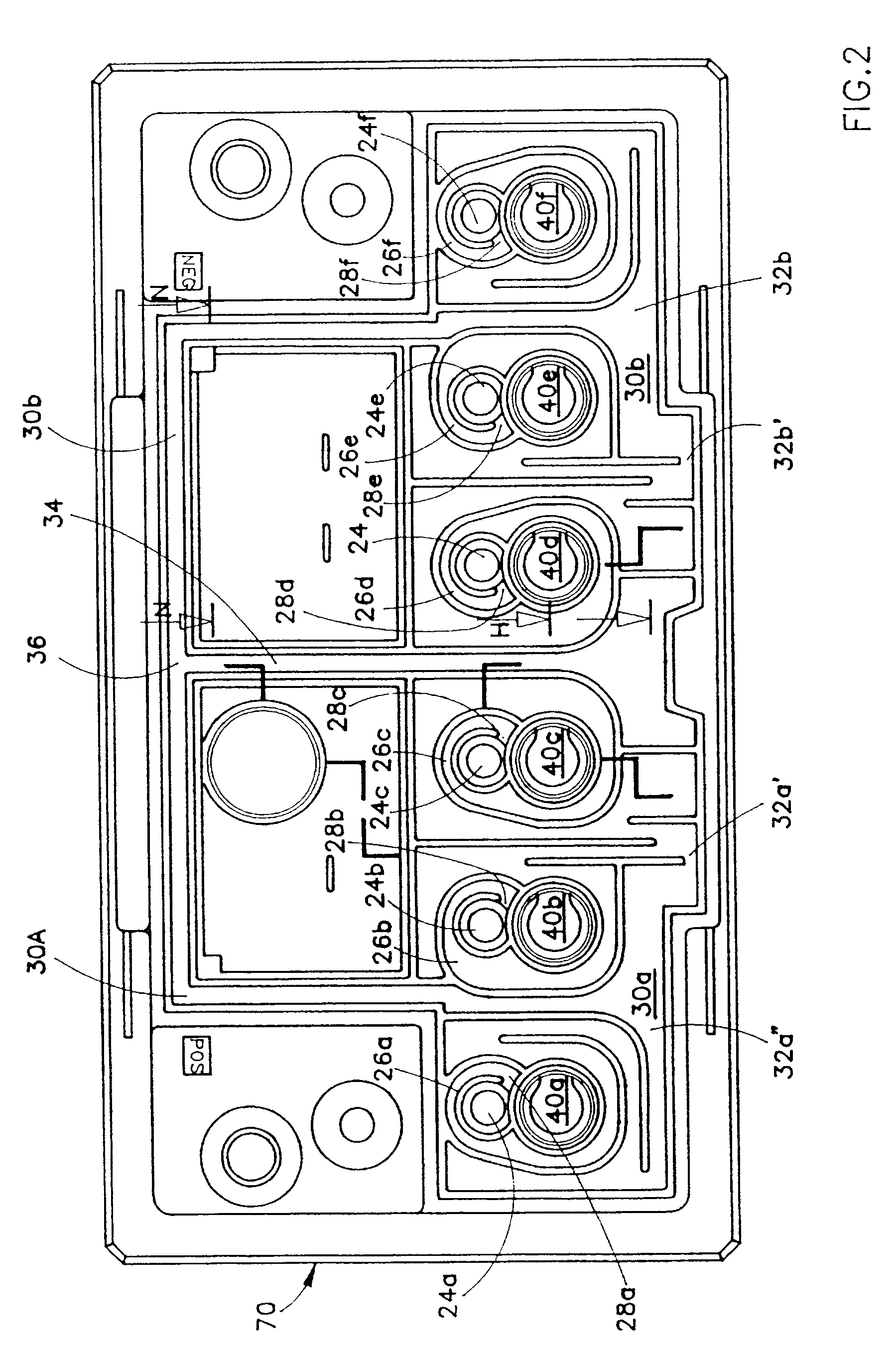
When electrolyte gas escapes through cell vent 22, it communicates into an initial passage 26 of the labyrinth 20 through a passage entrance 28. Each cell 18 is associated with one initial passage 26A-F and one passage entrance 28A-F. The initial passage 26 ultimately leads to atmosphere. Multiple initial passages 26A-F converge into a first common passage 30 at a first convergent point 32. Although there may be many convergent points, the first embodiment initially brings two passages 26B-C, 26D-E together at the first convergent point 32A', 32B'. The paths from the outermost initial passages 26A, 26F join at points 32A" and 32B", respectively. Thus, the first common passages 30A', 30B' form a portion of the path to atmosphere for three cells 18A-C, 18D-F, respectively. The two first common passages 30A', 30B' ultimately combine to form a final common passage 34 at a final convergence point 36. The path to atmosphere for each cell 18 is provided by the final common passage 34. The ...

second embodiment

FIG. 4 shows the battery cover constructed according to the present invention. As with the embodiment in FIG. 2, electrolyte gases escape through cell vents 122, communicate into an initial passage 126 of the labyrinth 120 through a passage entrance 128 and converges into a first common passage 130A, 130B at a first convergent point 132A, 132B. The three initial passages 126A-C, 126D-F for each side of the battery converge into the common passages 130A, 130B, at convergence points 132A, 132B, respectively. The common passage 130A ultimately combines with a similar common passage 130B from the other half of the battery to form a final common passage 134 at a final convergent point 136.

FIG. 13 shows yet a further cover embodiment. Similar to the earlier embodiments, the third embodiment allows electrolyte gas to escape through a cell vent 222 into an initial passage 226 through a passage entrance 228. In the third embodiment, the initial passages 226A, 226B and 226C converge into a fi...


PUM

PropertyMeasurementUnit
areaaaaaaaaaaa
resistanceaaaaaaaaaa
heataaaaaaaaaa

Abstract

The present invention is directed to a leak resistant battery cover for storage batteries. The battery cover provides a labyrinth of passages which provide a path from each cell vent to the atmospheric vent. The labyrinth is configured to provide a portion of each path above a level in which the electrolyte in the respective cells attains when the battery is tipped on any one of its sides or rotated ninety (90) degrees from an upright position. The labyrinth configuration prevents electrolyte from reaching the atmospheric vent and spilling out of the battery.

Description

BACKGROUND OF THE INVENTION(1) Field of the InventionThe invention relates to a storage battery cover, and more particularly to a storage battery cover offering added protection against leakage when a battery using the cover of the invention is tipped to any one of its sides or inverted.(2) Description of the Prior ArtConventional storage batteries include a battery housing having a housing and a cover for closing an open top end of the casing. The battery housing is a rectangular casing having multiple compartments or cells for receiving cell plates and electrolyte therein. The cover device is heat sealed to an open top end of the battery housing casing.The cover device often includes a main cover part and a sub-cover part. The main cover part has a horizontally disposed plate body with a top face formed by a rectangular confining wall. The confining wall is divided by multiple partitions and associated chambers. The main cover further includes multiple service ports for pouring el...

Claims


Application Information

Patent Timeline
Patent Type & Authority Patents(United States)
IPC IPC(8): H01M2/12H01M2/36H01M2/00H01M50/367
CPCY02E60/10H01M50/394H01M50/668H01M50/367
Inventor FRITTS, ROBERT W.REVAK, DAVID M.
Owner DOUGLAS BATTERY MFG
Why Eureka
Eureka Blog
Learn More