Electronic controller for scheduling device activation by sensing daylight

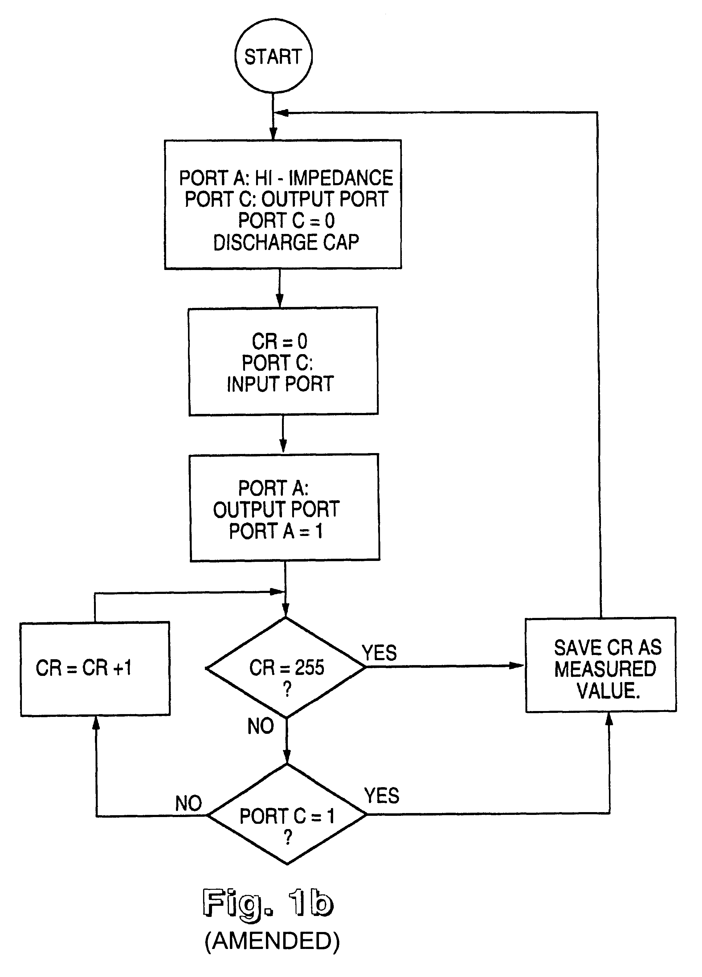
a technology of electronic controller and scheduling device, applied in the direction of programme control, optical radiation measurement, instruments, etc., can solve the problem that the amount of incident light may never be sufficient to produce a reading of cr=0

Inactive Publication Date: 2003-03-18
FLAMBEAU
View PDF11 Cites 15 Cited by
  • Summary
  • Abstract
  • Description
  • Claims
  • Application Information

AI Technical Summary

Benefits of technology

Particularly, in prior art, a game feeder that was to activate one hour before sunset, was not achieved. The reason was that the prior methods did not employ an internal time representation that spanned anything but a short period of time. An important means taught in this invention is the employment of long term hysteresis, spanning on the order of one day or more. The advantage can be clearly seen in the example given where sunset is anticipated, with confidence, to next occur at time `139` in the mod256 counter. We can activate a device approximately one hour before sunset by triggering activation when the mod256 counter equals the number 139 minus one hour. One hour on the mod256 counter resolves to a count of 60 / 5.625=10.6. Rounding 10.6 to 11, the firmware program in the microcontroller would subtract 11 from the sunset time of 139, to yield a count of 128. To activate the device when the mod256 counter equals 128 will result in activation very close to one hour before sunset, or 6PM in this example.
This example given is most appropriate for an application of feeding wildlife with a game feeder, and the advantage gained allowing feeding one hour before sunset. A modification of this example in order to show how application could be made to outside lighting is given next.

Problems solved by technology

For a particular package, with a particular orientation, and a particular phototransistor, the amount of incident light may never be sufficient to produce a reading of CR=0.

Method used


Image

  • Electronic controller for scheduling device activation by sensing daylight
  • Electronic controller for scheduling device activation by sensing daylight
  • Electronic controller for scheduling device activation by sensing daylight

Examples


Embodiment Construction

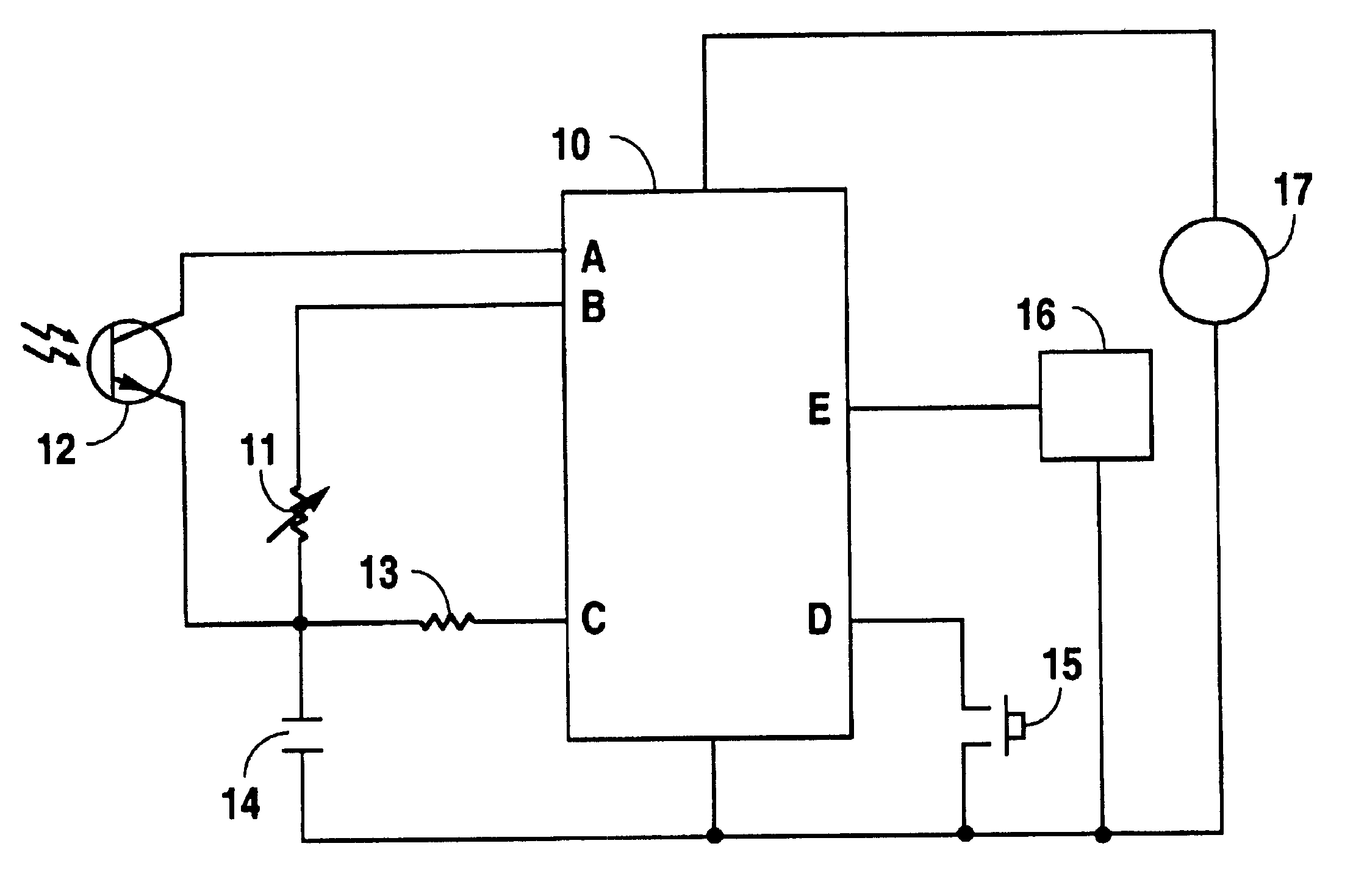
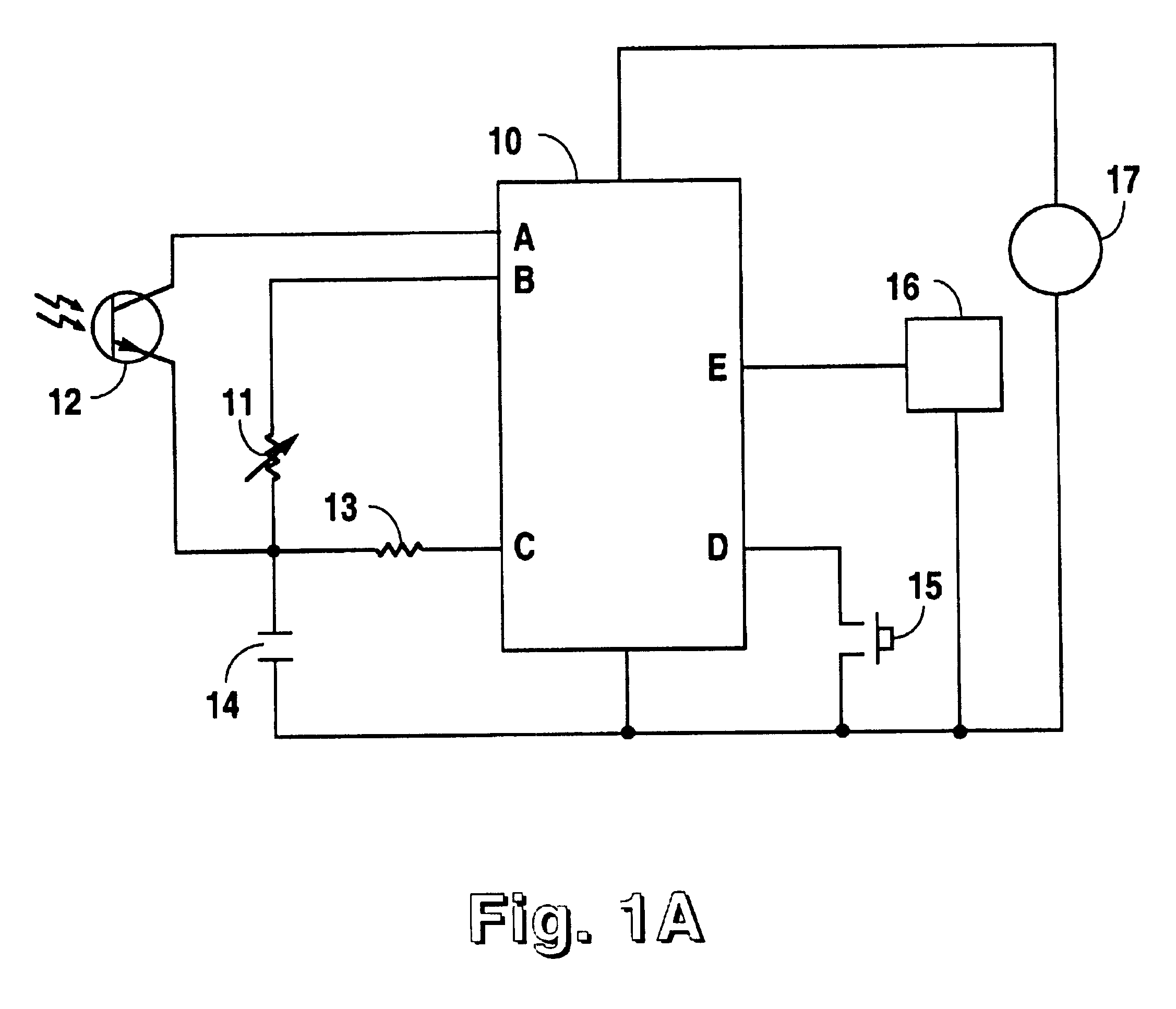
An embodiment of the light detection apparatus for controlling the activation of a device is given in FIG. 1a. A source of power, 17, supplies electronic circuit 10, which is preferred to be an embedded microcontroller. An appropriate microcontroller for this application could be the brand and model: Microchip PIC16C54. The wires marked A and B on the microcontroller 10, are digital output ports. The wire marked C on 10 is a port that can be either an input or output, and this sense can be switched dynamically under program control. The wire on 10 marked E is an output port. The wire marked D is an input port to the microcontroller. The FIG. 1a connections show that the output port A is connected to a light sensor, such as a phototransistor 12, which connects to a capacitor, 14, attached to the common side of the power source. Similarly, connections illustrated show that the output port B is connected to a potentiometer, 11, which connects to the same capacitor 14. At the point wher...


PUM


Abstract

A device controller synchronizes a counter to the detection of sunrise or sunset by photoelectrically sensing daylight, thereby establishing an approximate time reference for scheduling the timing of device activations to occur at any time of day or night. An uncalibrated method of measuring sunlight yields more reliable scheduling, relative to sunrise and sunset events. The integral approximate time reference is kept synchronized, even if occasional faults in detection of sunrise or sunset occur. The rules employed to establish and maintain synchronization, and the dynamically variable rules of evaluating changes in light intensity, contribute to the reliable performance of the controller apparatus. Inherently self-adapting and automatic, a potentiometer for setting a time parameter input and a push-button for setting a time parameter input are combined in the apparatus in such a way to yield further utility without complicating the programmability. Additionally, for animal feeder applications, a test mode utilizes <DEL-S DATE="20030318" ID="DEL-S-00001"/>a modulates<DEL-E ID="DEL-S-00001"/> activation of the feed motor to produce audible warning of imminent motor activation.

Description

BACKGROUND1. Field of InventionThis invention relates to electronic timers and photoelectric controllers used to control electric lighting, activate animal feeders, control irrigation, or other timed control activation apparatus, where daylight sensing is used as a timing cue.2. Discussion of Prior ArtElectric or electronic timer apparatus often used for controlling devices need to be set with the proper time, both initially and upon replacing a battery or after the time wanders for some reason. In some applications, having to set the time could require that personnel reach inaccessible places.Another class of device controllers operates on sensing daylight. Where timing is based relative to the amount of ambient daylight, these prior art device controllers do not employ an internal time clock. They rely upon the natural cycle of the day and night. The driving function of these controllers, after all, is the amount of light, not the absolute time.Photoelectric controls have long bee...

Claims


Application Information

Patent Timeline
Patent Type & Authority Patents(United States)
IPC IPC(8): G05B19/042G05B19/04H05B37/02
CPCG05B19/0426G05B2219/23196G05B2219/25278G05B2219/37117H05B47/11H05B47/16Y02B20/40
Inventor NEUMANN, RODNEY H.
Owner FLAMBEAU
Why Eureka
Try Eureka