One-way clutch apparatus

Inactive Publication Date: 2004-04-20
MEANS IND INC
View PDF25 Cites 26 Cited by
  • Summary
  • Abstract
  • Description
  • Claims
  • Application Information

AI Technical Summary

Benefits of technology

To allow the above-described close placement of portions of the surface of the driven member relative to the arms of the key, the arms of the key are formed with ramp portions thereon to provide a degree of relief to the arm portions. This degree of relief enables a front end portion of the key to be urged outwardly by a biasing member, such as a spring, and to engage a recess in the driven member when the driving member is rotated in a driving direction (i.e., a direction wherein the key will engage the driven member and drive the driven member rotatably therewith). The ramp portions formed on the arms of the key provide the needed clearance between the arm portions and the portions of the surface of the driven member which would otherwise interfere with the movement of the key or enough for the ramp portions. The ramp portions formed

Problems solved by technology

This lubrication requirement becomes more difficult to satisfy as the transmission or other apparatus within which the one-way clutch is disposed is oriented in different angles, such as when a vehicle or aircraft associated with the transmission incorporating the one-way clutch changes its attitude relative to the earth's surface.
In such instances there may be momentary lapses of lubrication to the notches wherein the struts are housed.
These lapses, in some extreme instances, could adversely impact the wear of the one-wa

Method used


Image

  • One-way clutch apparatus
  • One-way clutch apparatus
  • One-way clutch apparatus

Examples


Embodiment Construction

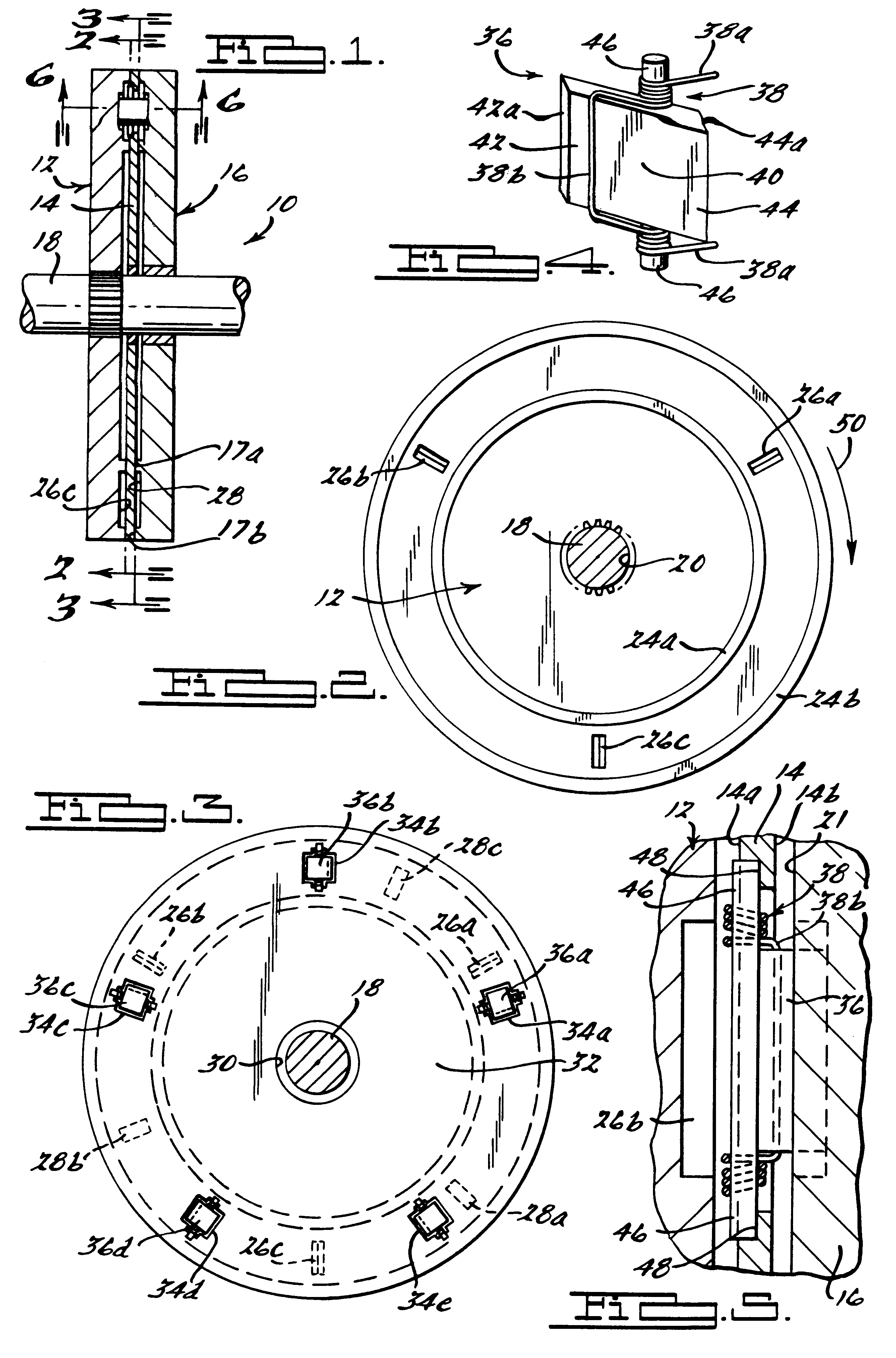
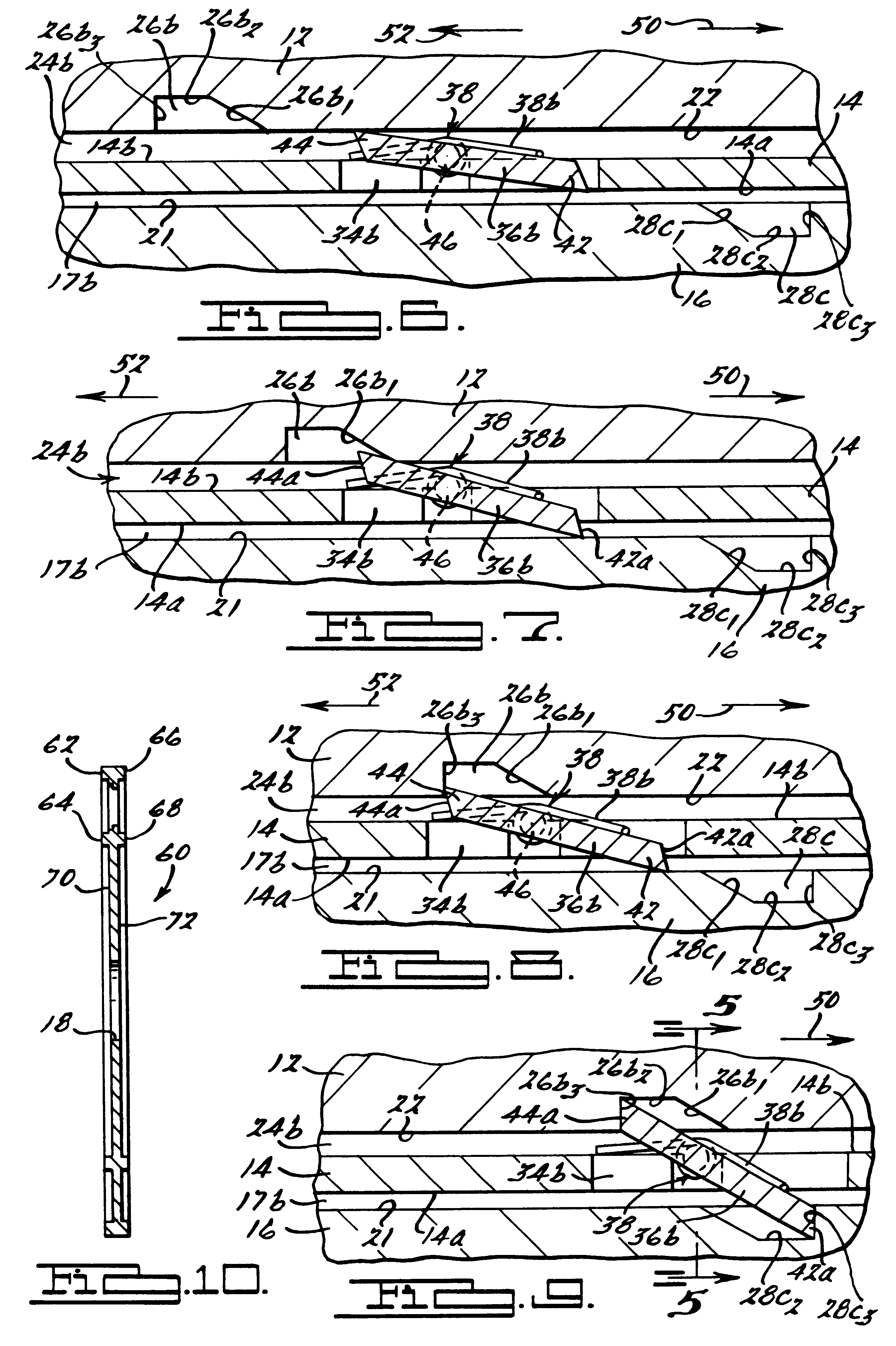
Referring to FIG. 1, there is shown a one-way clutch apparatus 10 in accordance with a preferred embodiment of the present invention. The apparatus 10 generally includes a driving member 12 in the form of a drive plate or disk, a carrier plate 14 in the form of a plate or disc, and a driven member 16 in the form of a driven plate or disk. For purposes of illustration, the driving plate 12 is shown splined to a drive shaft 18 such that rotational movement of the drive shaft 18 causes a corresponding rotational movement of the driving member 12. Also for purposes of illustration, the carrier plate 14 and driven member 16 are shown concentrically disposed about the drive shaft 18 such that each is free to remain stationary when the one-way clutch 10 is not engaged. It will be appreciated that the driving member 12 and driven member 16 could just as easily be switched such that member 16 imparts a motive force to member 12. Furthermore, it should be appreciated that one or the other of ...


PUM


Abstract

A one-way clutch apparatus comprising a driving member having a plurality of recesses, a corresponding plurality of biasing members disposed in the recess, a corresponding number of keys or struts disposed over the biasing members in the recesses, and a driven member having a plurality of key-engaging notches formed circumferentially about an inside surface. Each of the keys includes a pair of laterally protruding arm portions and each of the arm portions has a ramp formed thereon which acts as a relief to allow the inside surface of the driven member to be placed to close proximate relationship with the inside surface of a driving member and to overlay portions of the recess. The overlaying enables the driven member to damp or otherwise limit the movement of a back end portion of each key when the driving member is moved in either a free-wheeling direction or driving direction, while the ramp portions allow a front end portion of the key to be urged outwardly without any portion of the arm portion interfering with the inside surface of the driven member overlaying portions of each recess. The one-way clutch apparatus is not as dependent upon a copious and continuous supply of lubricant to damp unwanted movement of the key as prior art developed one-way clutch systems.

Description

TECHNICAL FIELDThis invention relates to clutches, and more particularly to a one-way clutch apparatus.DISCUSSIONClutches are used in a wide variety of applications to selectively couple power from an input member, such as a driving disk or plate, to a second independently rotatable member such as a driven plate or disk. In some applications, it is further desirable to incorporate a clutch which allows for rotational movement of the driving member in a second rotational direction in which no clutch engagement occurs, and therefore in which no rotation of the driven member occurs. Such clutches are commonly referred to as "one-way" clutches. With a one-way clutch, when a driving member is rotated in a first direction, the clutch causes engagement of the driving member with an external driven member. When the driving member is rotated in a second rotational direction opposite to that of the first rotational direction, the clutch releases the driven member from engagement with the driv...

Claims


Application Information

Patent Timeline
IPC IPC(8): F16D41/12F16D41/00
CPCF16D41/125Y10T74/2136
Inventor RUTH, STEPHEN M.KLECKER, BRIAN D.FRANK, A. RICHARD
Owner MEANS IND INC
Why Eureka
Try Eureka