Component shelf system

a shelf system and component technology, applied in the field of shelves, can solve the problems of reducing the amount of useable storage space, destroying shelves no longer needed, and creating problems, so as to increase the stability of the entire shelf, prevent lateral movement of the vertical edges, and ensure the effect of stability

Inactive Publication Date: 2005-03-01
MERKEL RAIMUND
View PDF12 Cites 52 Cited by
  • Summary
  • Abstract
  • Description
  • Claims
  • Application Information

AI Technical Summary

Benefits of technology

To achieve these objects, stabilizing elements such as angle sections, screws or rivets have been eliminated. This yields surfaces that extend around the compartment divisions with no sharp edges. Furthermore, in the junctions between the horizontal and vertical compartment divisions, a splint is inserted between the parts of the folded vertical compartment division. This not only increases the stability of the entire shelf with the horizontal compartment divisions, but safely prevents lateral movement of the vertical edges of the vertical compartment divisions.
The invention makes use of two tabs with bores which are arranged on the edges of the side wall and on the horizontal and vertical compartment divisions, through which securing bars are installed in the assembled shelf. Thus it is possible to assure an extremely stable connection between the components of the shelf when the components are assembled and fixed by the securing bars.

Problems solved by technology

Because of its overall construction, this known rack, which is made from corrugated board, is only suitable for receiving goods of a light weight.
In the corner areas of the compartments, support sections, securing elements or other applications lead to interfering edges that may cause problems when the compartments of the shelf are loaded with sensitive goods, or when the latter are removed from the shelf.
In addition, the securing elements may reduce the amount of useable storage space.
Furthermore, disposal of those shelves which are no longer needed creates problems.

Method used


Image

  • Component shelf system
  • Component shelf system
  • Component shelf system

Examples


Embodiment Construction

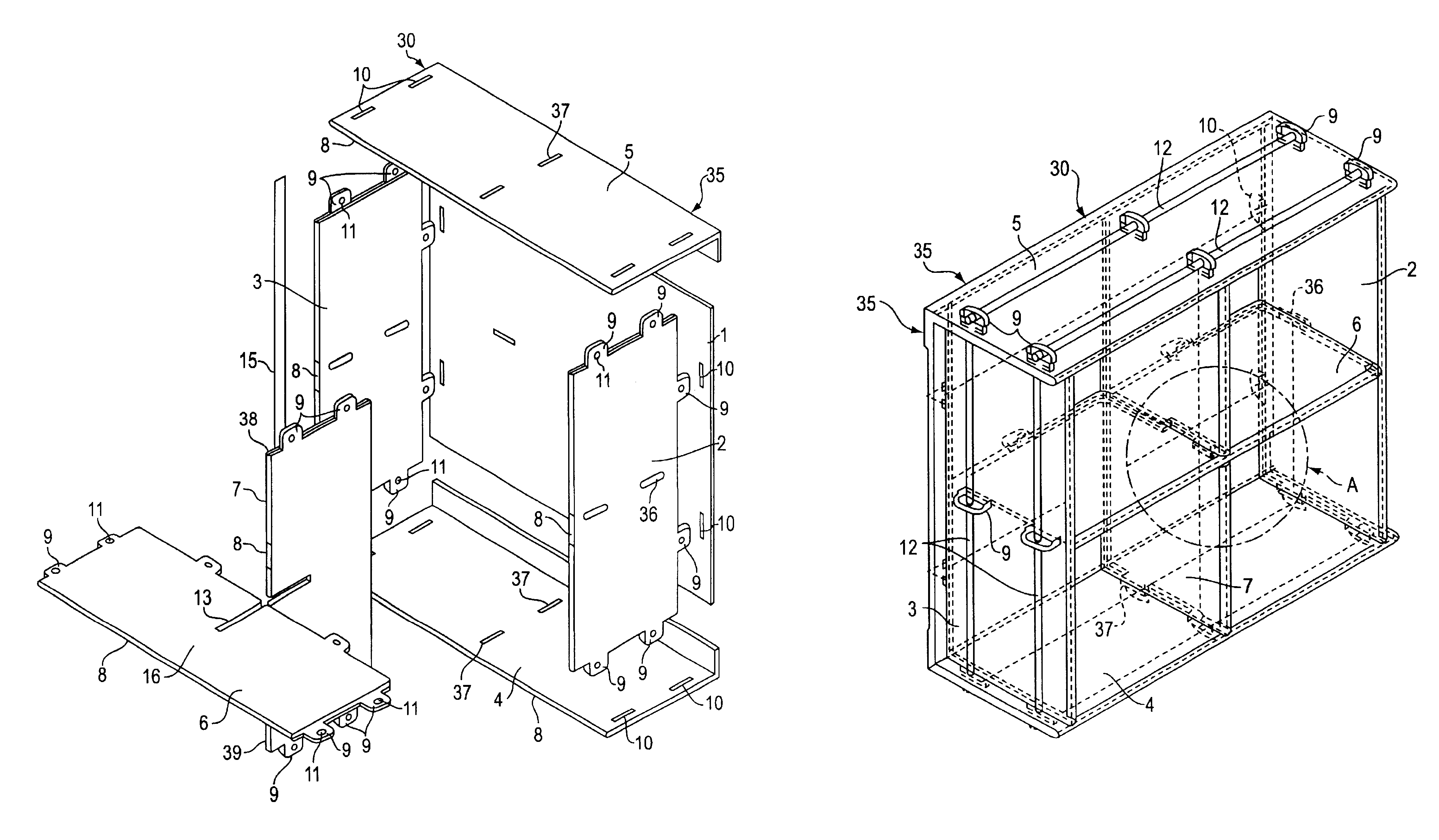
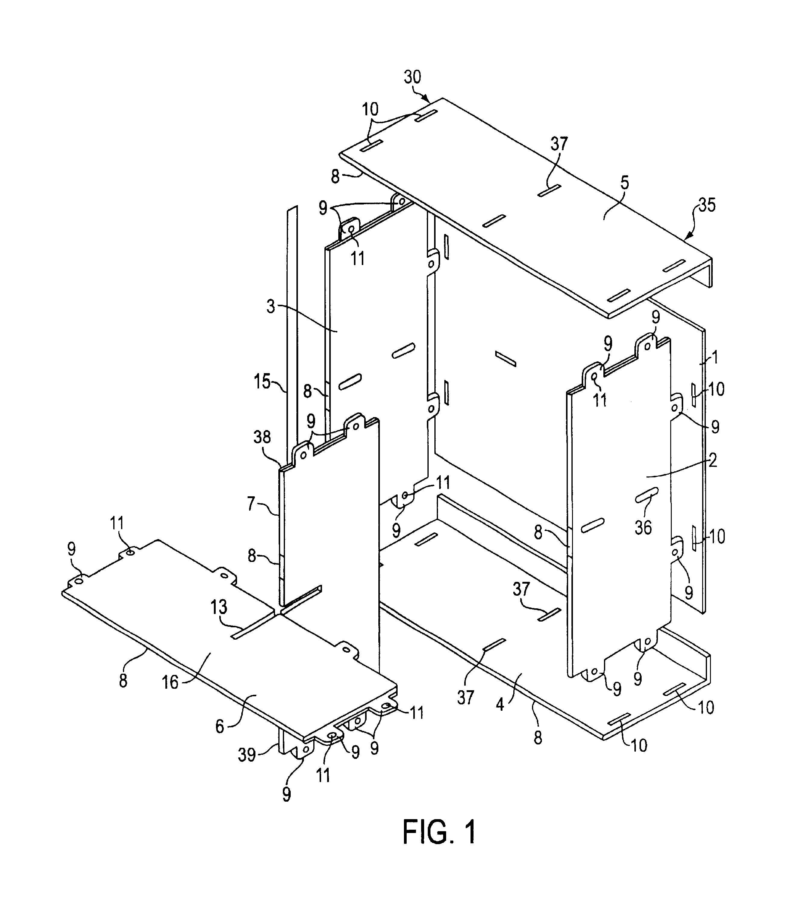
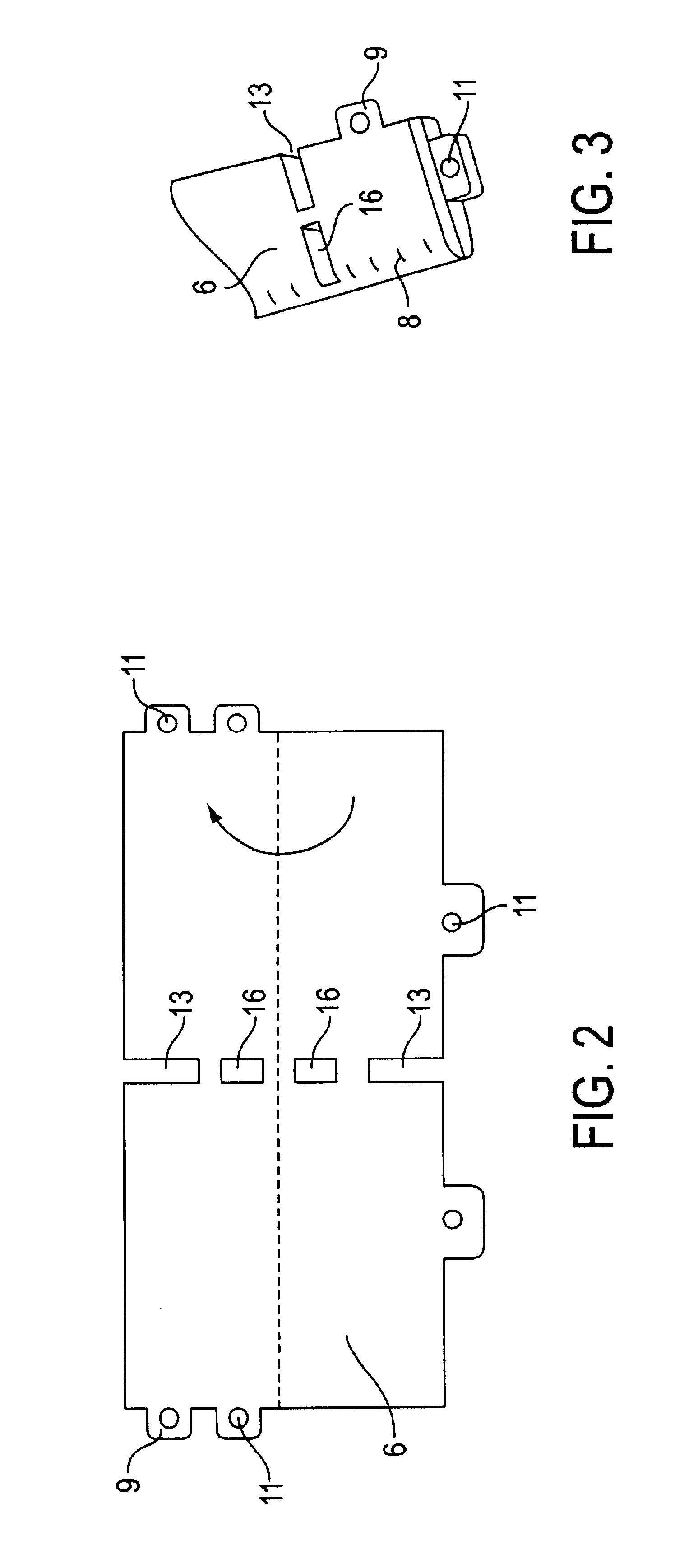
Turning now in detail to the drawings, FIG. 1 shows a component shelf system 30 comprising a frame 35 having a back wall 1, a pair of side walls 2 and 3, a bottom wall 4, and a top wall 5; at least one horizontal compartment divider 6, and at least one vertical compartment divider 7 having a top end 38 and a bottom end 39. Note that only one compartment divider is shown in each case for the sake of simplicity.

Side walls 2 and 3, top wall 5, bottom wall 4 as well as the horizontal compartment divider 6 and vertical compartment divider 7 consist of folded rectangularly shaped cuts from cellular plastic boards each forming a rounded folding edge 8. Using this process, the shelf does not have any sharp edges on the circumferential surfaces of the stabilizing elements or the like as the edges 8 are always rounded.

Side walls 2 and 3 contain at least one horizontal receiving slot 36 and at least one tab 9. Horizontal compartment divider 6 and vertical compartment divider 7 each have at lea...


PUM

PropertyMeasurementUnit
diameteraaaaaaaaaa
angleaaaaaaaaaa
weightaaaaaaaaaa

Abstract

The invention relates to shelving, in particular, shelving consisting of components which are assembled with securing elements. The invention contains a frame having a back wall, a pair of side walls, a top wall and a bottom wall attached to each other with a plurality of tabs and corresponding slots located on the back wall, side walls, top wall and bottom wall. The back wall, side walls, top wall and bottom wall are constructed of folded material which provides rounded edges that limit damage to material stored on the shelf. A securing bore is located on each of the tabs and is milled to a particular diameter corresponding to the type of material used to construct the shelf and the load supported. A plurality of safety bars are inserted through the securing bore located on each of the tabs. The safety bars prevent the removal of the tabs from the corresponding slots and help secure the shelf. In addition, horizontal and vertical compartment divider may be attached to the frame using the same tab and slot method. The additional compartment divides allow for an unlimited number of compartments.

Description

BACKGROUND OF THE INVENTION1. Field of the InventionThe present invention relates to shelving, in particular, shelving consisting of components which are assembled with securing elements and further comprising vertical and horizontal compartment dividers.2. The Prior ArtIt is known in the art to connect shelves consisting of individual components such as horizontal and vertical compartment dividers, shelf posts and back walls by means of screws, rivets, or by welding. A method frequently employed for assembling shelves comprises securing the shelf bottoms with screws between vertical posts. Another frequently used method is to suspend so-called compartment supports in vertical posts, or to screw such supports into the latter. The individual compartment bottoms are then secured to such supports by means of screws.Another method for constructing shelves makes use of mounting supports, such as angle sections which are located on vertical walls on the left and right sides having defined...

Claims


Application Information

Patent Timeline
Patent Type & Authority Patents(United States)
IPC IPC(8): A47F5/00A47B43/02A47B47/00A47B47/04A47B96/04
CPCA47B47/042A47B2230/0096F16B12/24
Inventor MERKEL, RAIMUND
Owner MERKEL RAIMUND
Why Eureka
Try Eureka