Shower bath apparatus and spray nozzle

a technology of showering apparatus and spray nozzle, which is applied in the field of showering apparatus, can solve the problems of narrow spay angle, insufficient swirl force of fluid, and difficult to obtain relaxation feeling of showering, so as to reduce the loss of swirl force, and suppress the heat of the user.

Inactive Publication Date: 2005-10-25
MATSUSHITA ELECTRIC WORKS LTD
View PDF27 Cites 7 Cited by
  • Summary
  • Abstract
  • Description
  • Claims
  • Application Information

AI Technical Summary

Benefits of technology

[0064]In a shower bath apparatus in a forty-eighth aspect of the invention, the water reforming means is composed of carbon dioxide generating means and carbon dioxide dissolving means for dissolving carbon dioxide generated from the carbon dioxide generating means, and carbon dioxide is generated by the carbon dioxide generating means, out of the carbon dioxide generating means and carbon dioxide dissolving means of the water reforming means, and the carbon dioxide is dissolved in hot water by the carbon dioxide dissolving means, and hot water containing carbon dioxide is sprayed to the skin of the body surface from the spray nozzle connected to the passage, consumption of hot water is smaller as compared with bath tub bathing, and the required amount of carbon dioxide is smaller, so that shower bath with carbonate spa effect is realized.
[0065]In a shower bath apparatus in a forty-ninth aspect of the invention, a detachable water tank for collecting water spray is disposed in the foot area of the body, and when the user takes a shower bath in a relaxed state sitting on the chair or the like, plural spray nozzles disposed around the body inject hot water in mist form to envelop the user, and the hot water film and hot water spray are collected in the detachable water tank disposed in the foot area of the body, so that the sprayed hot water can be used as foot bath while taking a comfortable spray shower bath.
[0066]In a shower bath apparatus in a fiftieth aspect of the invention, draft means for blowing cold air to the head is disposed, and therefore by blowing cold air to the head area of the body by the draft means during or after shower bath by the spray nozzle, the head and face are cooled by cold air, and the heat of the user can be suppressed, so that fresh and comfortable shower life can be enjoyed.
[0067]In a fifty-first aspect of the invention, the spray nozzle includes a flow passage, three swirl units for swirling the fluid incoming from the flow passage, and an injection hole disposed at the downstream side of the swirl units for injecting the swirling fluid, in which the three swirl units act to swirl the incoming fluid to provide the fluid with a swirl force, while the flows from the swirl units from the swirl units to the injection hole hardly interfere with each other to be stabilized and reduce the loss of swirl force, and the swirl force of the fluid is large at the injection hole, and the mist particles are smaller in size at low pressure, and the spray angle is wider.
[0068]In a fifty-second aspect of the invention, three swirl units of the spray nozzle are formed as swirl holes, and the constitution of the swirl units is simplified, and the pressure loss of the fluid and the loss of swirl force generated by the swirl units are suppressed to a minimum limit, so that a stabler spraying is realized at lower cost.

Problems solved by technology

Shower bath is becoming popular as simple bathing means owing to its ease in preparation for bathing and saving of space, but shower bathing is hard to get warmth and obtain relaxed feeling, and there is a gap from the bath tub bathing practice based on the traditional bath culture in Japan.
In such conventional spray nozzle, however, since only two swirl holes 7 are provided in the swirl unit 3, sufficient swirl force of fluid is not obtained, and the spay angle is narrow and mist particles are rough in size.
In particular, when used at low pressure as in general household, the swirl force of fluid is much smaller, and mist particles are small in the conventional nozzle, and it is hard to realize a nozzle with a large spray angle.
To solve this problem, by reducing the size of the injection hole of the nozzle, a nozzle reduced in mist particle size and widened in spray angle has been proposed, but since the pressure loss is large, sufficient fluid flow rate is not obtained, and hence the application is limited to spraying of agricultural chemicals or the like.
In Japanese Laid-open Patent No. 8-38377 allowing an elderly user weak in physical strength to have shower in seated position, not in standing position very large in burden, there is no aid for standing or sitting, and the burden due to standing or sitting before and after bathing occurs.
It is also a problem that the nozzle provided on the floor is an obstacle when moving within the bath room.

Method used


Image

  • Shower bath apparatus and spray nozzle
  • Shower bath apparatus and spray nozzle
  • Shower bath apparatus and spray nozzle

Examples


embodiment 1

[0120](1) Embodiment 1

[0121]Referring now to FIG. 1, embodiment 1 of the invention is described below.

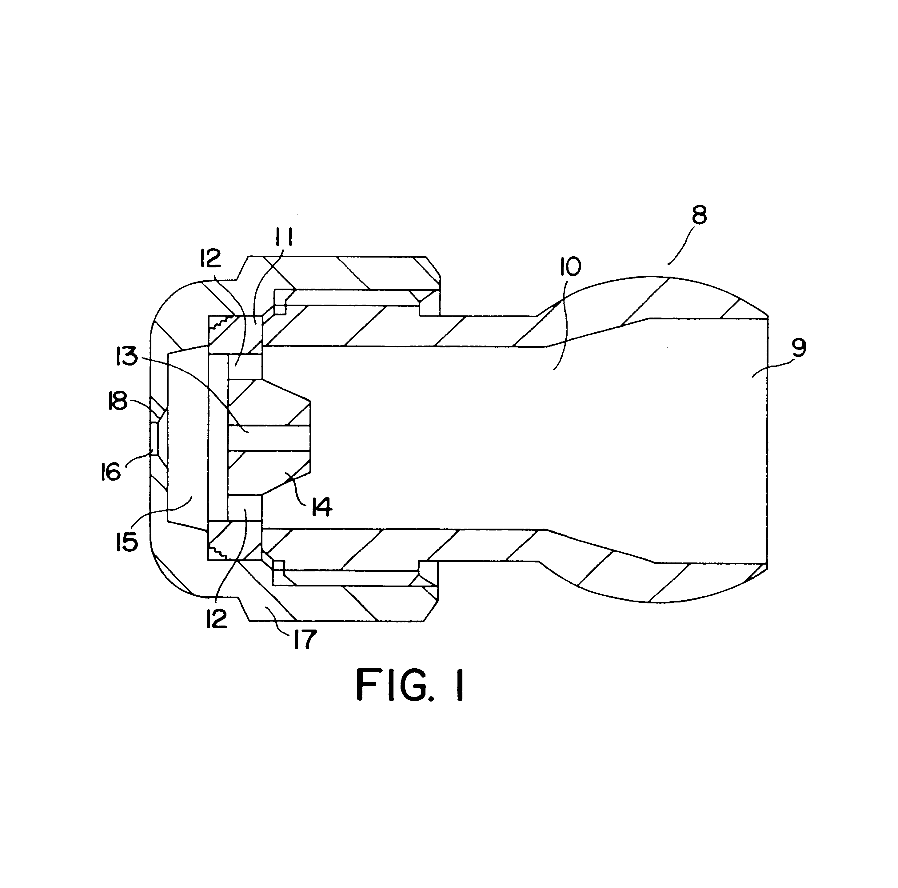
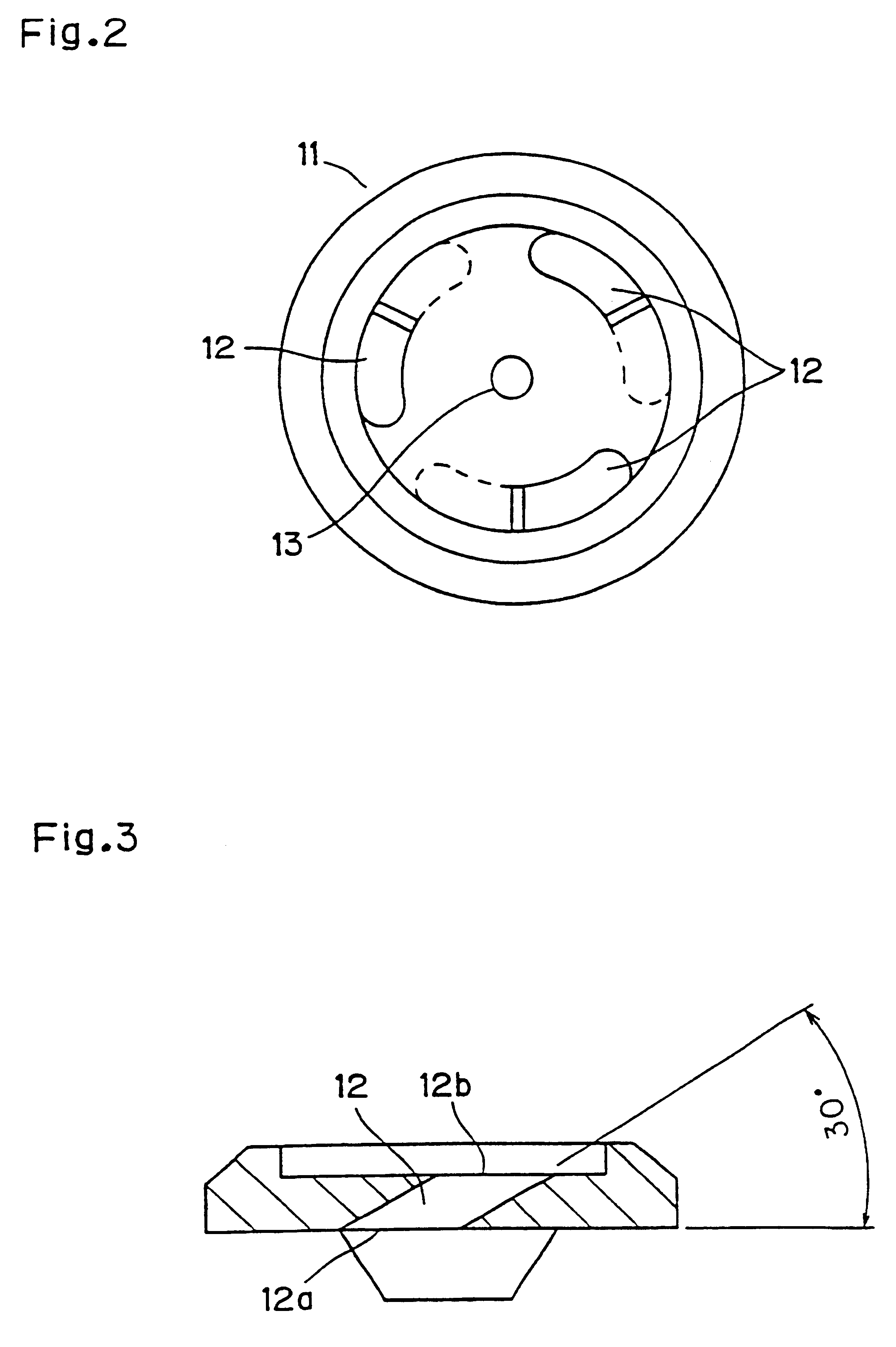
[0122]FIG. 1 is a sectional view of spray nozzle in embodiment 1 of the invention.

[0123]In FIG. 1, a flow inlet 9 and a flow passage 10 through which fluid flows are provided in a nozzle main body 8. Reference numeral 11 is a swirl tip for swirling the fluid flowing in through the flow passage 10, and as shown in FIG. 2, moreover, swirl holes 12 are disposed as swirl units at three positions on the circumference, while a central hole 13 is provided nearly in the center of the swirl holes. The three swirl holes 12 are equal in the opening area and are provided to divide the circumference in three equal sections so that the swirl flows coming out of the swirl holes 12 may be uniform. The swirl holes 12 are, in order to increase the opening area and heighten the swirl force, in a slender shape centered on the circumference in which the three swirl holes 12 are provided. FIG. 3 is a par...

embodiment 2

[0136](2) Embodiment 2

[0137]Embodiment 2 of the invention is described below while referring to FIGS. 6 and 7.

[0138]FIG. 6 is a sectional view of a spray nozzle in embodiment 2, and FIG. 7 is an appearance drawing of a swirl tip 11. In embodiment 2, what differs from embodiment 1 is that the central hole 13 is not provided in the center of the three swirl holes 12 of the swirl tip 11.

[0139]In this constitution, only the action different from embodiment 1 is described. The incoming fluid reaches the swirl tip 11, and is equally divided into three swirl holes 12. The fluid does not form central axial flow, but when the flow rate is the same, the generated swirl force is increased by the increment portion of the swirl flow rate. Therefore, the swirl force of the jet flow passing through the injection hole 16 increases, and the spray angle is further increased at low flow rate and low pressure.

[0140]Incidentally, when the injection hole 16 is formed smoothly without chamfering portion 1...

embodiment 3

[0141](3) Embodiment 3

[0142]Embodiment 3 of the invention is described below by referring to FIG. 8, referring only to the difference from embodiment 1. FIG. 8 is a sectional view of the spray nozzle of embodiment 3.

[0143]In FIG. 8, a nozzle main body 19 is provided with a flow inlet 9 and a flow passage 10 through which the fluid flows in, and at the flow-out side of the flow passage 10, swirl holes 20 are provided as swirl units at three positions on the same circumference, together with a central hole 21 nearly in the center of swirl hole. The nozzle main body 19 has a nozzle cap 17 forming an injection hole 16 for injecting the fluid, which is engaged with a threaded portion 22 as spray variable means, and by rotating the nozzle cap 17, the distance of swirl holes 20 and injection hole16 can be adjusted. A seal member 23 is provided at the junction of the nozzle main body 19 and the nozzle cap 17, and leak of fluid from the threaded portion 22 is prevented.

[0144]Reference numera...


PUM


Abstract

A shower bath apparatus which enables hot water bathing in a relaxed condition and provides a warm feeling over the whole body, equivalent to bathing in a bath tub. The shower bath apparatus comprises a shower bath apparatus body, a seat, on which a bathing person is seated, a spray nozzle for jetting hot water to the bathing person, and an arm provided with at least one spray nozzle. Sprayed hot water envelops the whole body of a user in a seated position to give the user a warm feeling.

Description

[0001]This is a Reissue Application of U.S. Pat. No. 6,195,814, issued Mar. 6, 2001.[0002]This Application is a U.S. National Phase Application of PCT International Application PCT / JP97 / 00525.TECHNICAL FIELD[0003]The present invention relates to a shower bath apparatus having a spray nozzle for jetting fluid to a user, and more particularly to a shower bath apparatus capable of warming the whole body simultaneously same as bathing in a bath tub, and bringing about an excellent warming effect.BACKGROUND ART[0004]Shower bath is becoming popular as simple bathing means owing to its ease in preparation for bathing and saving of space, but shower bathing is hard to get warmth and obtain relaxed feeling, and there is a gap from the bath tub bathing practice based on the traditional bath culture in Japan. To eliminate this gap, various shower bath apparatuses have been proposed. For example, Japanese Laid-open Patent No. 61-94616 proposes a shower box as shown in FIG. 43, in which a ring-s...

Claims


Application Information

Patent Timeline
Patent Type & Authority Patents(United States)
IPC IPC(8): A47K3/28A61H33/02E03C1/06
CPCA47K3/282A47K3/286A61H33/02A61H33/60E03C1/06A47K3/26
Inventor YOSHIDA, HIROAKISHIRAI, SHIGERUKAWAGURI, MASAAKIKAWAHARA, KAZUSHIGEINAGI, MASAAKIYAMAMOTO, MASAKIGYOKUSEN, HIROFUMI
Owner MATSUSHITA ELECTRIC WORKS LTD
Why Eureka
Try Eureka