System for signatureless transmission and reception of data packets between computer networks

a data packet and computer network technology, applied in the field of data packet security, can solve the problem that no one on the public internetwork can determine the contents of packets

Inactive Publication Date: 2006-10-17
SUN MICROSYSTEMS INC
View PDF8 Cites 151 Cited by
  • Summary
  • Abstract
  • Description
  • Claims
  • Application Information

AI Technical Summary

Problems solved by technology

In this way, no one on the public internetwork can determine the contents of the packets.

Method used


Image

  • System for signatureless transmission and reception of data packets between computer networks
  • System for signatureless transmission and reception of data packets between computer networks
  • System for signatureless transmission and reception of data packets between computer networks

Examples


Embodiment Construction

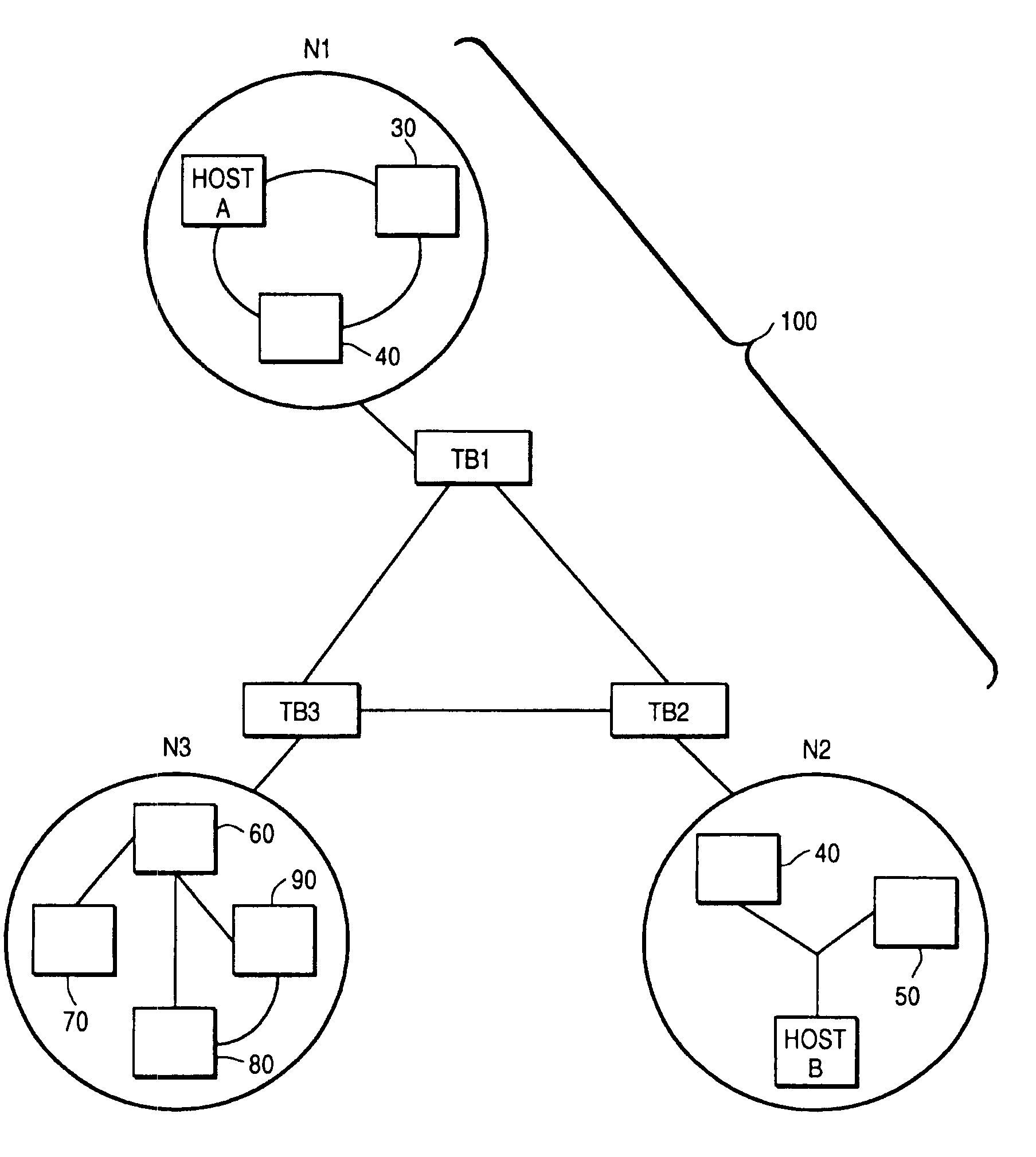
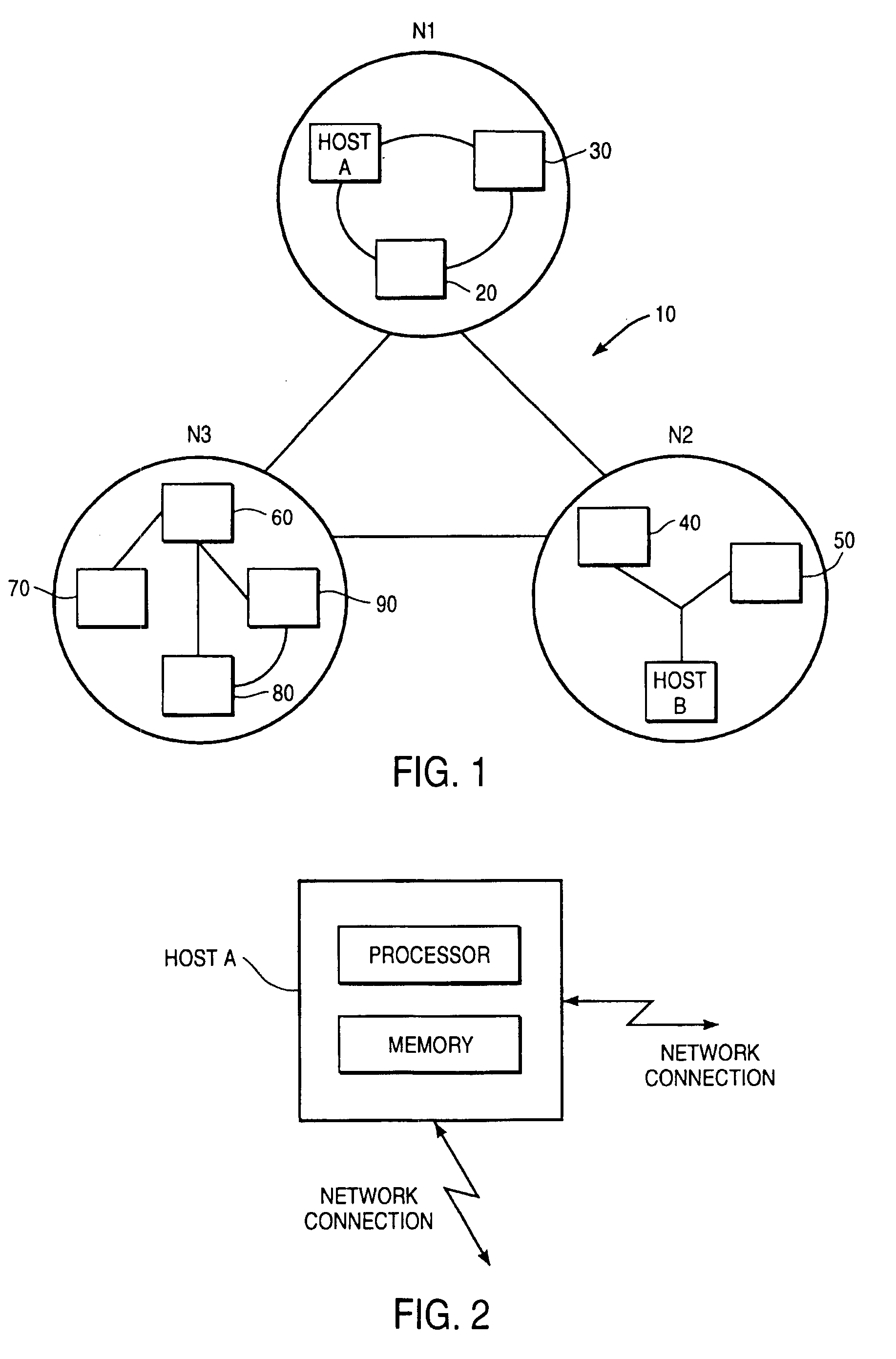
[0023]The system of the present invention is designed to be implemented in existing computer networks, and in the preferred embodiment uses the addition of a tunnelling bridge at junctions between local computer networks and public or larger-scale networks such as the Internet. The mechanisms for carrying out the method of the invention are implemented by computers acting as these tunnelling bridges, incorporating program instructions stored in memories of the tunnelling bridges and appropriate (standard) network connections and communications protocols.

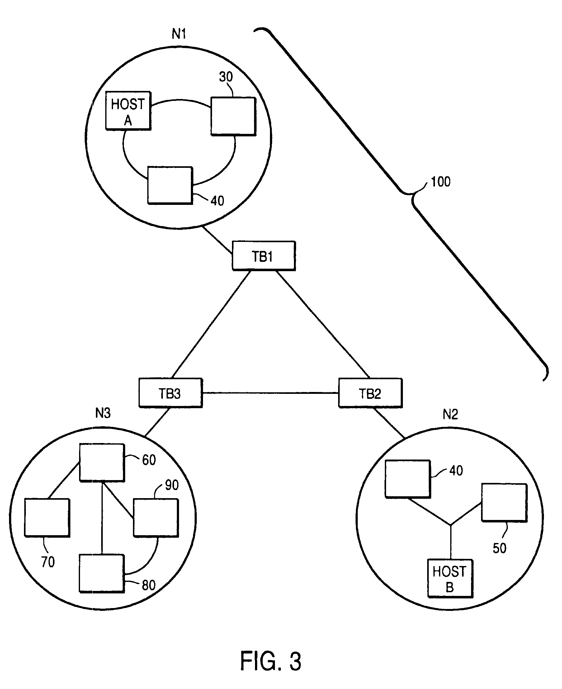
[0024]FIG. 3 shows a network 100 of networks N1, N2 and N3 according to the invention, where each network includes a tunnelling bridge—TB1, TB2 and TB3, respectively—which intercepts all data packets from or to the respective networks. Networks N1-N3 may in other respects be identical to networks N1-N3 in conventional designs. In the following description, any references to networks N1-N3 or hosts A and B should be taken as referring...


PUM


Abstract

A system for automatically encrypting and decrypting data packet sent from a source host to a destination host across a public internetwork. A tunnelling bridge is positioned at each network, and intercepts all packets transmitted to or from its associated network. The tunnelling bridge includes tables indicated pairs of hosts or pairs of networks between which packets should be encrypted. When a packet is transmitted from a first host, the tunnelling bridge of that host's network intercepts the packet, and determines from its header information whether packets from that host that are directed to the specified destination host should be encrypted; or, alternatively, whether packets from the source host's network that are directed to the destination host's network should be encrypted. If so, the packet is encrypted, and transmitted to the destination network along with an encapsulation header indicating source and destination information: either source and destination host addresses, or the broadcast addresses of the source and destination networks (in the latter case, concealing by encryption the hosts' respective addresses). An identifier of the source network's tunnelling bridge may also be included in the encapsulation header. At the destination network, the associated tunnelling bridge intercepts the packet, inspects the encapsulation header, from an internal table determines whether the packet was encrypted, and from either the source (host or network) address or the tunnelling bridge identifier determines whether and how the packet was encrypted. If the packet was encrypted, it is now decrypted using a key stored in the destination tunnelling bridge's memory, and is sent on to the destination host. The tunnelling bridge identifier is used particularly in an embodiment where a given network has more than one tunnelling bridge, and hence multiple possible encryption / decryption schemes and keys. In an alternative embodiment, the automatic encryption and decryption may be carried out by the source and destination hosts themselves, without the use of additional tunnelling bridges, in which case the encapsulation header includes the source and destination host addresses.

Description

[0001]Cross-reference is made to U.S. application Ser. No. 10 / 147,933 which is a continuation Reissue Application of U.S. Pat. No. 5,548,646.BACKGROUND OF THE INVENTION[0002]The present invention relates to the field of secure transmission of data packets, and in particular to a new system for automatically encrypting and decrypting data packets between sites on the Internet or other networks of computer networks.[0003]It is becoming increasingly useful for businesses to transmit sensitive information via networks such as the Internet from one site to another, and concomitantly more urgent that such information be secured from uninvited eyes as it traverses the internetwork. At present, unsecured data is replicated at many sites in the process of being transmitted to a destination site, and trade secret or other private information, unless secured, is thereby made available to the public.[0004]It is possible for a user at the sending host to encrypt the data to be sent, and to infor...

Claims


Application Information

Patent Timeline
Patent Type & Authority Patents(United States)
IPC IPC(8): H04L9/00G06F12/00H04L12/22H04L12/46H04L29/06
CPCH04L12/22H04L12/4625H04L63/0428H04L63/164H04L2212/00
Inventor AZIZ, ASHARMULLIGAN, GEOFFREYPATTERSON, MARTINSCOTT, GLENN
Owner SUN MICROSYSTEMS INC
Why Eureka
Try Eureka