Specification determining method, projection optical system making method and adjusting method, exposure apparatus and making method thereof, and computer system

a projection optical system and adjusting method technology, applied in the field of specification determining methods, can solve the problems of large amount of measurement and time, prior art methods of measuring and adjusting aberrations based on limited information hardly meet the demand for further improvement of exposure accuracy, and achieve high yield and high integration of micro-devices.

Inactive Publication Date: 2005-11-01
NIKON CORP
View PDF44 Cites 46 Cited by
  • Summary
  • Abstract
  • Description
  • Claims
  • Application Information

AI Technical Summary

Benefits of technology

[0027]This invention was made under such circumstances, and a first purpose of the present invention is to provide a specification determining method with which it is possible to simplify the process of making a projection optical system according to the determined specification and securely achieve a target that an optical apparatus with the projection optical system is to achieve.
[0028]Moreover, a second purpose of the present invention is to provide a projection optical system making method with which it is possible to simplify the process of making a projection optical system and securely achieve a target that an optical apparatus is to achieve.
[0029]A third purpose of the present invention is to provide an adjusting method which can accurately and easily adjust the optical characteristic of a projection optical system.

Problems solved by technology

However, because of the demand for further improved exposure accuracy corresponding to increasingly high integration in these years, measuring only the lower-order aberrations according to the prior art method and, based on the measuring result, adjusting the optical characteristic of the projection optical system does not yield a desired result.
Therefore, the prior art method of measuring and adjusting aberrations based on the limited information hardly meet the demand for further improved exposure accuracy.
In this case, although reticle patterns having intrinsic frequency components that are missing in the information need to be measured, it takes an enormous amount of measurement and time, so that it is not practical.
Furthermore, when an aberration is large, the linearity of the resist image to the corresponding space image of the pattern is lost, so that accurate measurement of the aberration is difficult.
It is because a projection optical system satisfying the specification determined obviously cannot achieve exposure accuracy demanded at present and in the future.
However, the above method of making a projection optical system needs the two steps of correcting lower-order aberrations and correcting higher-order aberrations and also computation for light-rays tracing that even super-computer will take several days to perform.
For example, when coma is large, the image of a pattern is not resolved, so that accurate data of distortion, astigmatism and spherical aberration cannot be obtained.
The fact that the order of measuring the aberrations to be adjusted is specified means that the selection of the lenses used is restricted.

Method used


Image

  • Specification determining method, projection optical system making method and adjusting method, exposure apparatus and making method thereof, and computer system
  • Specification determining method, projection optical system making method and adjusting method, exposure apparatus and making method thereof, and computer system
  • Specification determining method, projection optical system making method and adjusting method, exposure apparatus and making method thereof, and computer system

Examples


Embodiment Construction

[0120]An embodiment of the present invention will be described below based on FIGS. 1 to 11.

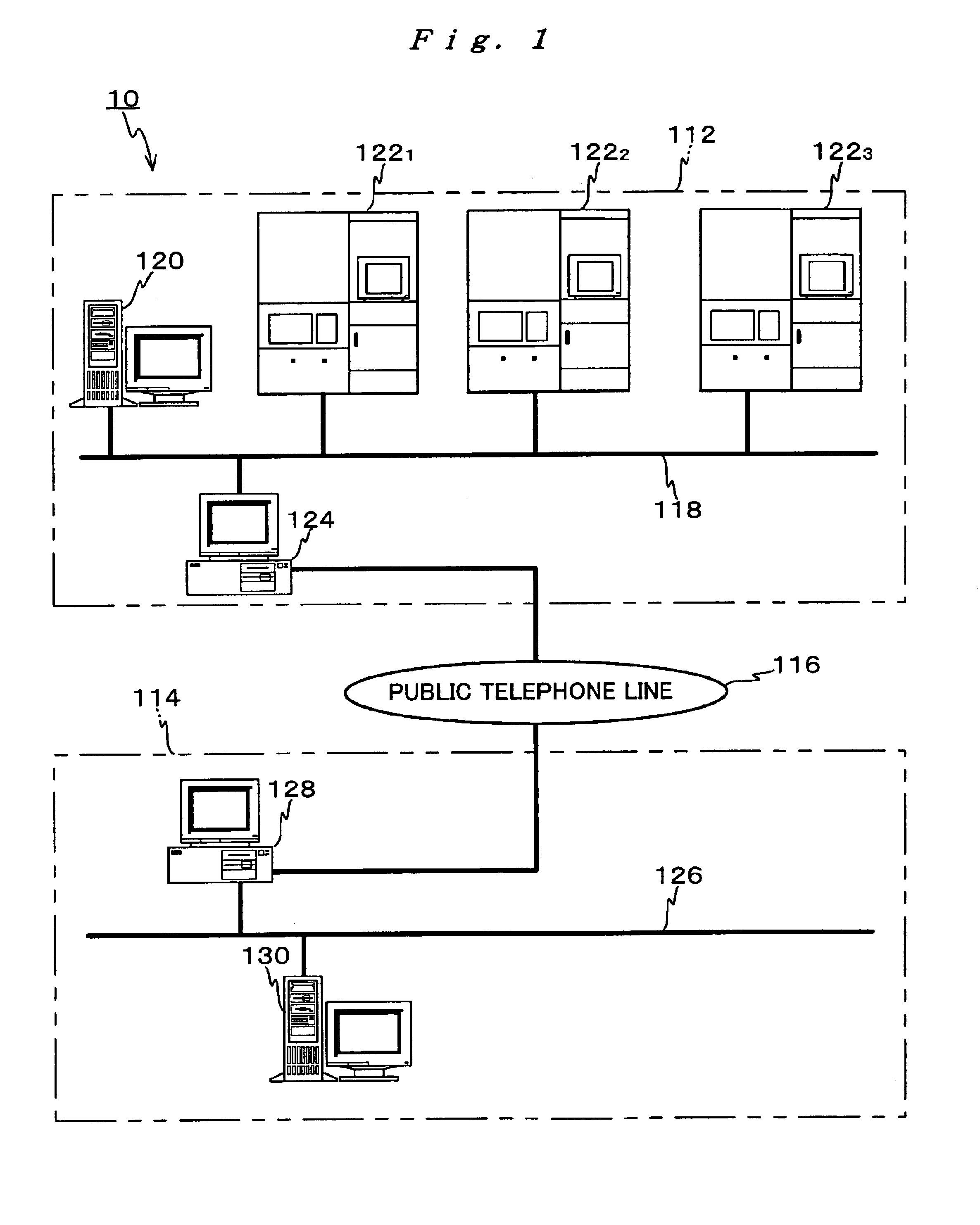
[0121]FIG. 1 shows the schematic construction of a computer system according to an embodiment of this invention.

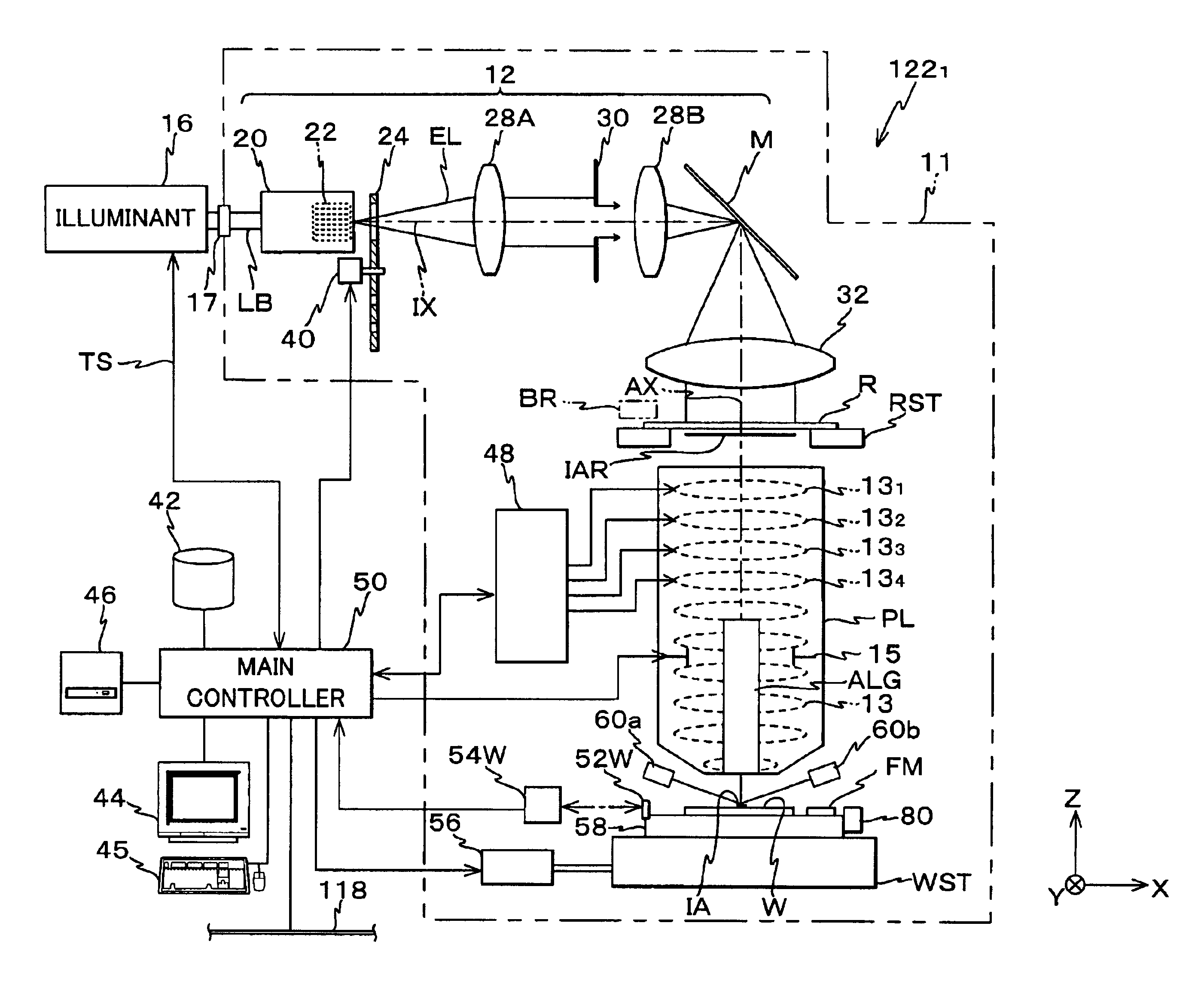
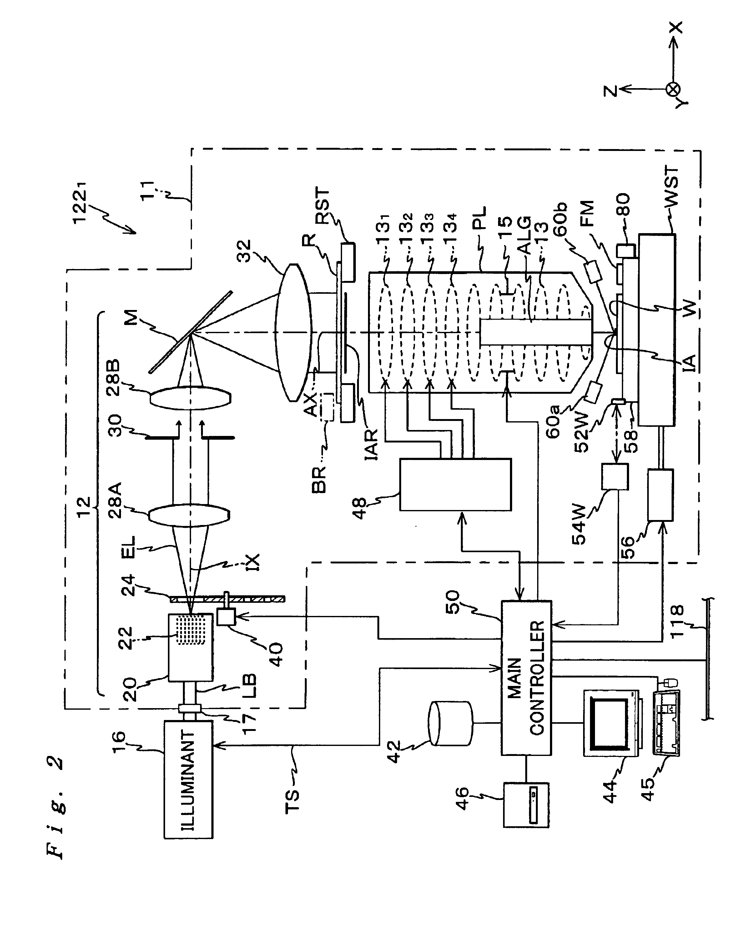
[0122]A computer system 10 shown in FIG. 1 comprises a lithography system 112 in a semiconductors-manufacturing factory of a device maker (hereinafter, called “maker A” as needed), which is a user of a device manufacturing apparatus such as an exposure apparatus, and a computer system 114 of an exposure apparatus maker (hereinafter, called “maker B” as needed) connected via a communication line including the public telephone line 116 to part of the lithography system 112.

[0123]The lithography system 112 comprises a communication server 120 as a first computer, a first, second and third exposure apparatuses 1221, 1222, 1223 as optical apparatuses, and a first proxy server 124 for verification, all of which are connected with each other via a local area network (LAN) 118.

[0124]The com...


PUM

PropertyMeasurementUnit
widthaaaaaaaaaa
widthaaaaaaaaaa
wavelengthaaaaaaaaaa

Abstract

A computer system comprises a first computer into which target information that an optical apparatus is to achieve is inputted and a second computer that determines the specification of a projection optical system based on the target information received from the first computer via a communication path with using a wave-front aberration amount, which the projection optical system is to satisfy, as a standard. Therefore, in the process of making the projection optical system, higher-order components of the aberration as well as lower-order components can be simultaneously corrected by adjusting the projection optical system based on the result of measuring the wave-front aberration to satisfy the specification, so that the making process becomes simpler. Furthermore, the target that the exposure apparatus is to achieve is securely achieved due to the projection optical system.

Description

BACKGROUND OF THE INVENTION[0001]1. Field of the Invention[0002]The present invention relates to a specification determining method, a projection optical system making method and adjusting method, an exposure apparatus and making method thereof, and a computer system, and more specifically to a specification determining method of determining the specification of a projection optical system to be provided in an optical apparatus, a method of making and a method of adjusting a projection optical system to be provided in an optical apparatus, an exposure apparatus provided with the projection optical system made according to the method of a projection optical system and making method thereof, and a computer system suitable for implementing the specification determining method and adjusting the imaging characteristic of the projection optical system provided in the exposure apparatus.[0003]2. Description of the Related Art[0004]In a lithography process for manufacturing semiconductor de...

Claims


Application Information

Patent Timeline
Patent Type & Authority Patents(United States)
IPC IPC(8): G03F7/20H01L21/027
CPCG03F7/706H01J2237/30433H01J2237/30461H01L21/027
Inventor HAMATANI, MASATOTSUKAKOSHI, TOSHIO
Owner NIKON CORP
Why Eureka
Try Eureka