Receptacle-mounted cover plate

a technology for receptacles and covers, applied in the direction of electrical apparatus, casings/cabinets/drawers, casings/cabinets/drawers details, etc., can solve the problems of limited decorator designs, relatively expensive, and low cost per unit, so as to eliminate the concerns of socket and cover plate alignment, the effect of reducing the cost per uni

Inactive Publication Date: 2008-12-09
HUBBELL INC
View PDF40 Cites 22 Cited by
  • Summary
  • Abstract
  • Description
  • Claims
  • Application Information

AI Technical Summary

Benefits of technology

[0011]Another object of the present invention is to provide an electrical outlet cover plate which is of relatively simple design and low cost.
[0012]Another object of the invention is to provide an electrical outlet cover plate which is relatively easy to assemble, align, clean and maintain.
[0023]Cover plates according to the invention can provide essentially the same appearance as decorator cover plate designs. In view of its unitary construction, however, this decorator look is achieved without the limitations of the actual decorator design as noted above. The cost on a unit basis can be significantly less than known decorator designs, not only for manufacture of the unit but also for application in replacement, remodeling, and the like. The unitary construction eliminates the previously-noted problems and limitations of receptacle face and cover plate alignment. The design, for example, is easy to install and eliminates socket and cover plate alignment concerns. It requires fewer components, thereby often reducing costs. It also can eliminate color discrepancies between socket faces and the cover plate which has been a difficulty with prior cover plates.

Problems solved by technology

The decorator designs have been limited, for example, in that they generally cannot be used with the commercially-known and widely-used yoke and dual socket receptacles mentioned above.
The decorator designs also have been disadvantageous in that they are relatively expensive.
Decorator design cover plates also are relatively more difficult than many other outlet designs to clean and maintain, in large part because of their two-component design.
Properly mating and accurately aligning the receptacle face with the cover plate also can be problematic.
However, the receptacle is not usually removed during remodeling or redecorating because it is hard-wired into the electrical system of the building.
Consequently, the receptacle and sockets are left exposed and the faces of the sockets can be stained with splattered paint and the like.
If not cleaned immediately, the receptacle face may become permanently defaced, thereby making the electrical outlet more unsightly and conspicuous.
Repeated paintings only make the problem worse.

Method used


Image

  • Receptacle-mounted cover plate
  • Receptacle-mounted cover plate
  • Receptacle-mounted cover plate

Examples


Embodiment Construction

[0035]Reference will now be made in detail to the presently preferred embodiment of the invention as illustrated in the accompanying drawings, in which like reference characters designate like or corresponding parts throughout the drawings and the various embodiments.

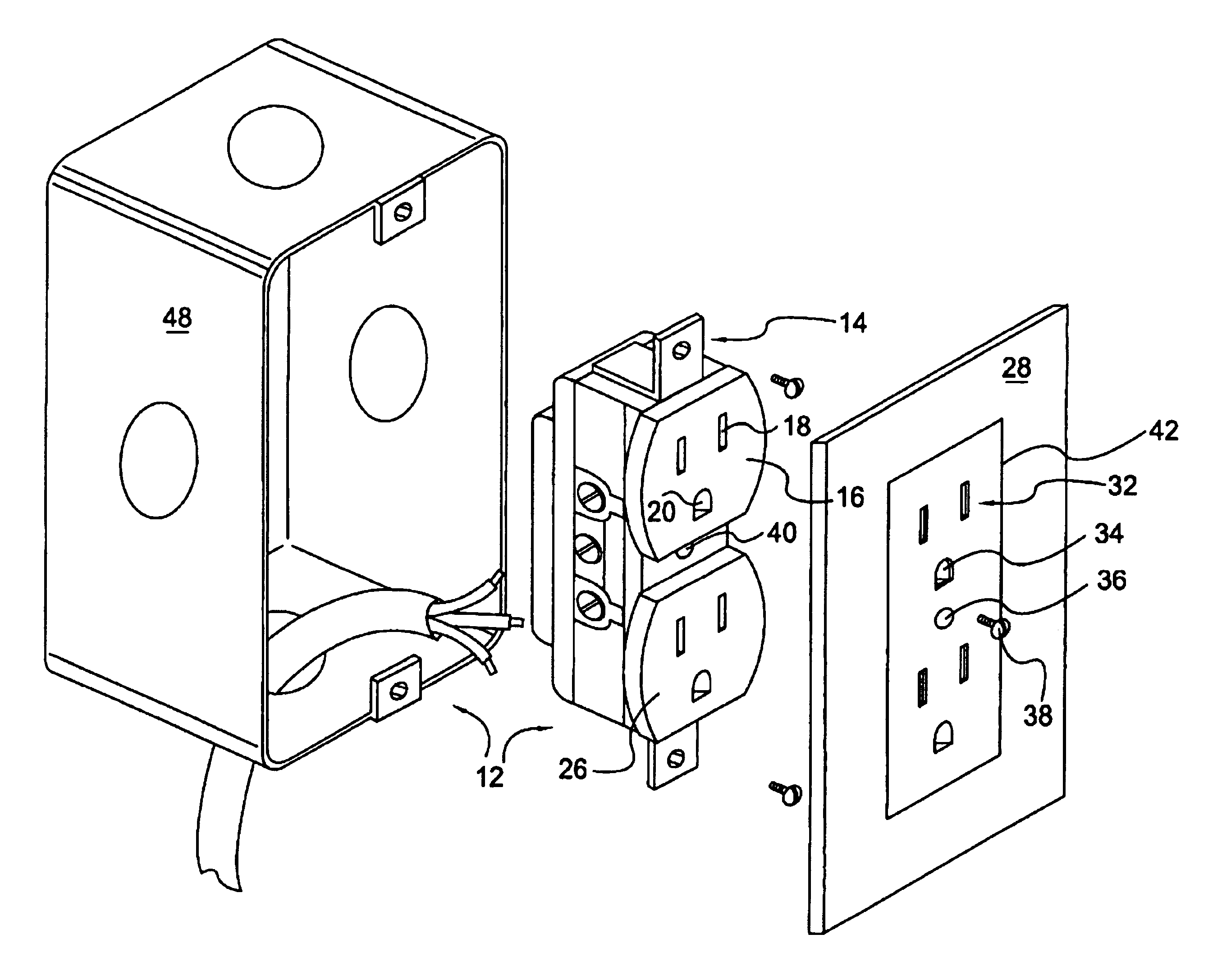
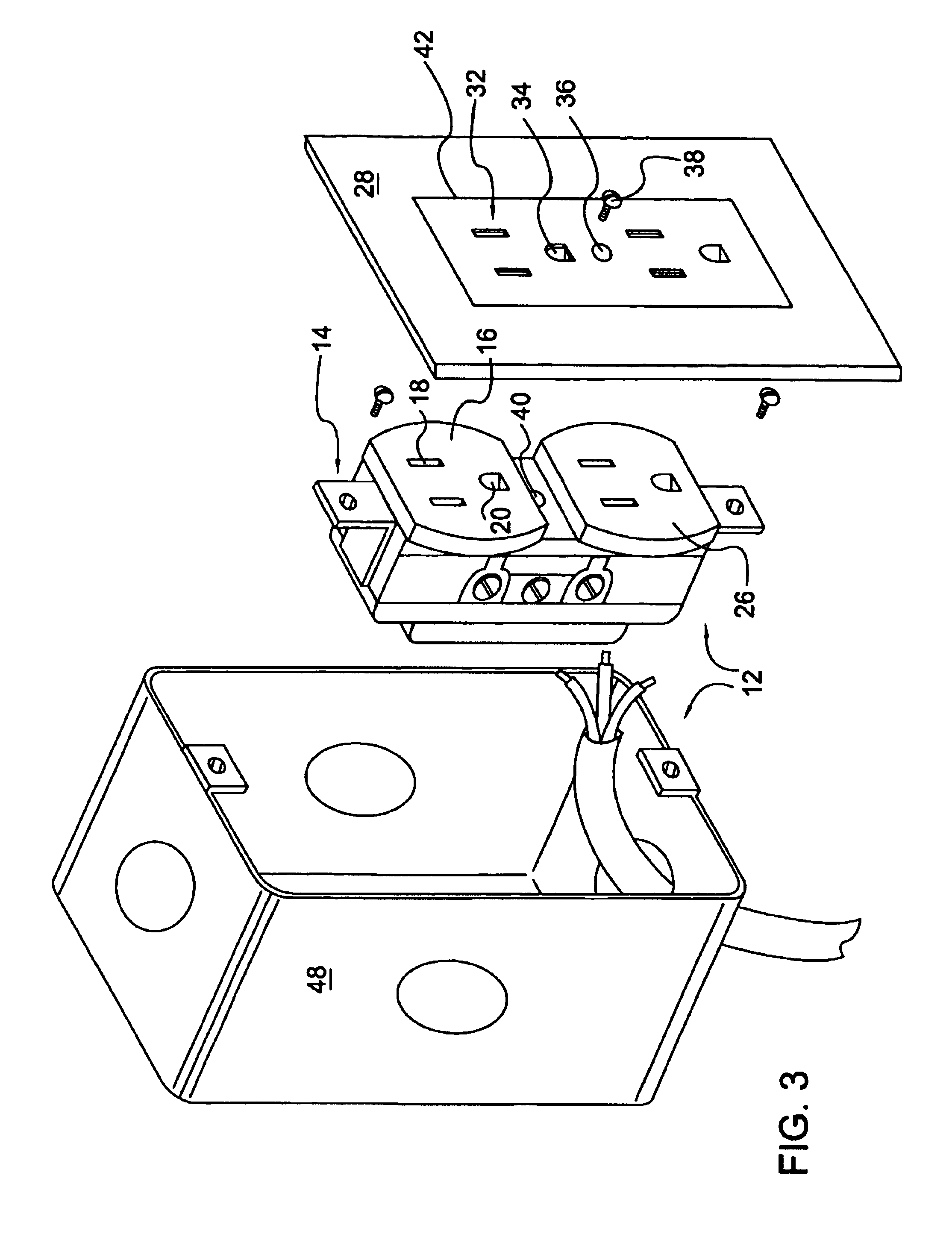
[0036]In accordance with the invention, a cover plate is provided for covering an electrical outlet. Typical electrical outlets for which cover plates according to the invention are well suited would include a receptacle having at least one socket and, optionally, at least one securing aperture for receiving a securing device. Each of the at least one socket includes a face and a plurality of blade apertures for receiving plug blades. The portion of the receptacle corresponding to the socket face is referred to in this document as the socket face.

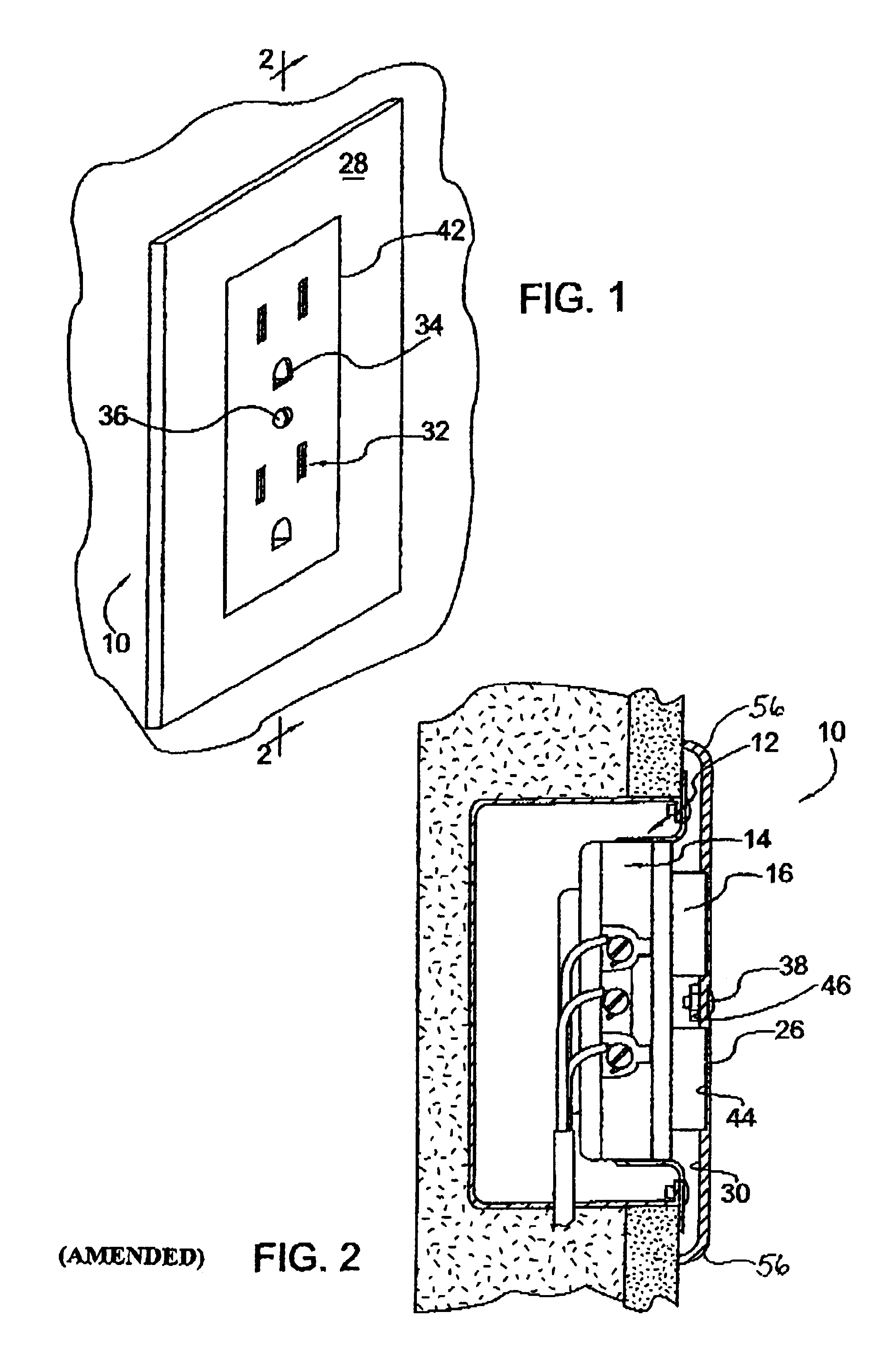
[0037]A cover plate 10 according to a presently preferred embodiment of the invention is shown in FIG. 1. Cover plate 10 is adapted to be attached to and cover an electrical ou...


PUM


Abstract

A cover plate for covering an electrical outlet. The electrical outlet includes a receptacle having at least one socket and at least one securing aperture for receiving a securing device, wherein each of the at least one socket includes a face and a plurality of blade apertures for receiving plug blades. The cover plate includes a front surface for facing outwardly from the electrical outlet and externally relative to the cover plate and a back surface facing toward the electrical outlet. A plurality of blade apertures extend through the cover plate through the front and back surfaces. Optionally, at least one securing aperture extends through the cover plate. The front surface of the cover plate contains, or includes, a single line extending substantially in a rectangle around the blade apertures and the at least one securing aperture, the front surface otherwise being continuous, having uniform topography, and being free of any other apertures. The cover plate is a single component and is solid except for the blade apertures and the at least one securing aperture. In accordance with another aspect, the front surface of the cover plate contains, or includes, a first substantially rectangular region, and a second region. The first region may be elevated or recessed with respect to the second region.

Description

[0001]This is a continuation-in-part of U.S. patent application Ser. No. 08 / 775,382, filed Dec. 30, 1996, now U.S. Pat. No. 5,965,846, which was a continuation of U.S. application Ser. No. 08 / 310,284, now abandoned.BACKGROUND OF THE INVENTION[0002]1. Field of the Invention[0003]The present invention relates generally to cover plates for electrical outlets, for example, such as those used in residential and commercial buildings. More specifically, it relates to cover plates for electrical outlets wherein the electrical outlet includes one or more sockets.[0004]2. Description of the Related Art[0005]Commercially-known and available electrical outlets for building applications, such as residential and commercial building outlets, typically include a wall box, a receptacle and a cover plate. The receptacle typically comprises a yoke with a pair of sockets incorporated into the yoke. The wall box usually is attached to a framing member, such as a wall stud, prior to placement of the inte...

Claims


Application Information

Patent Timeline
Patent Type & Authority Patents(United States)
IPC IPC(8): H02G3/14
CPCH02G3/126H02G3/14
Inventor MALTBY, EDGAR W.SHOTEY, MICHAEL
Owner HUBBELL INC
Why Eureka
Try Eureka