Methods and apparatus for scout-based cardiac calcification scoring

a cardiac calcification and scoring technology, applied in the field of scout-based cardiac calcification scoring, can solve the problems of major problems for cardiac calcification scoring, insufficient speed to avoid motion-induced image artifacts in cardiac ct imaging, and high cost of ct imaging systems employing scanning electron beams

Inactive Publication Date: 2008-12-16
GENERAL ELECTRIC CO
View PDF15 Cites 2 Cited by
  • Summary
  • Abstract
  • Description
  • Claims
  • Application Information

AI Technical Summary

Benefits of technology

[0007]There is therefore provided, in one embodiment of the present invention, a method for producing CT images of a patient's heart suitable for calcification scoring, in which the heart has a cardiac cycle. The method includes steps of acquiring data representative of a first scout-scanned CT image of physical locations of the patient's body including at least a portion of the patient's heart at phases φ1(L) of the cardiac cycle, acquiring data representative of a second scout-scanned CT image of the physical locations of the patient's body including at least a portion of the patient's heart at phases φ2(L) of the cardiac cycle different from φ1(L) at physi

Problems solved by technology

Although this speed is satisfactory for general imaging purposes, it is not fast enough to avoid motion-induced image artifacts in cardiac CT imaging, in which a typical cardiac cycle is about 1.0 s

Method used


Image

  • Methods and apparatus for scout-based cardiac calcification scoring
  • Methods and apparatus for scout-based cardiac calcification scoring
  • Methods and apparatus for scout-based cardiac calcification scoring

Examples


Embodiment Construction

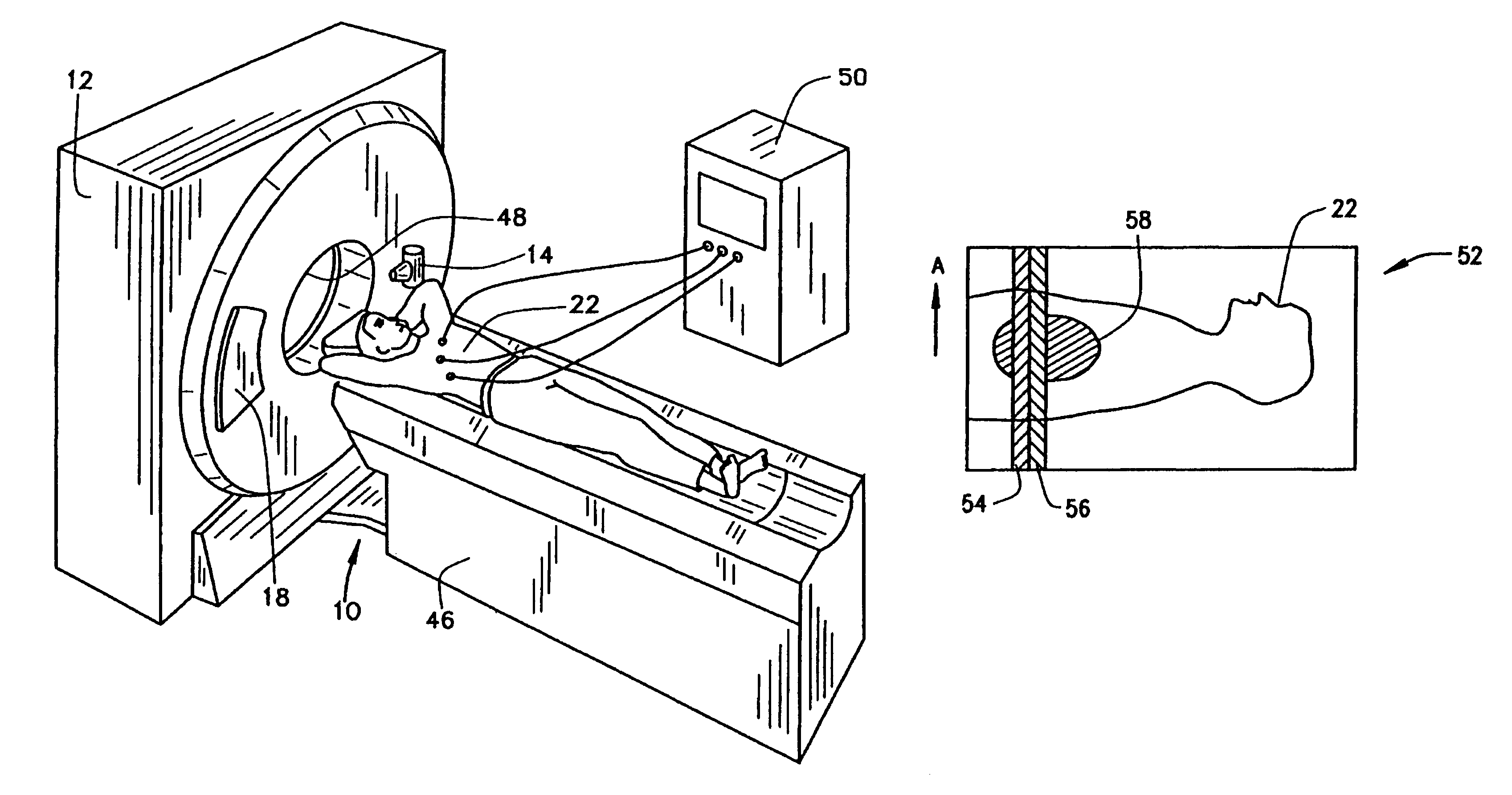
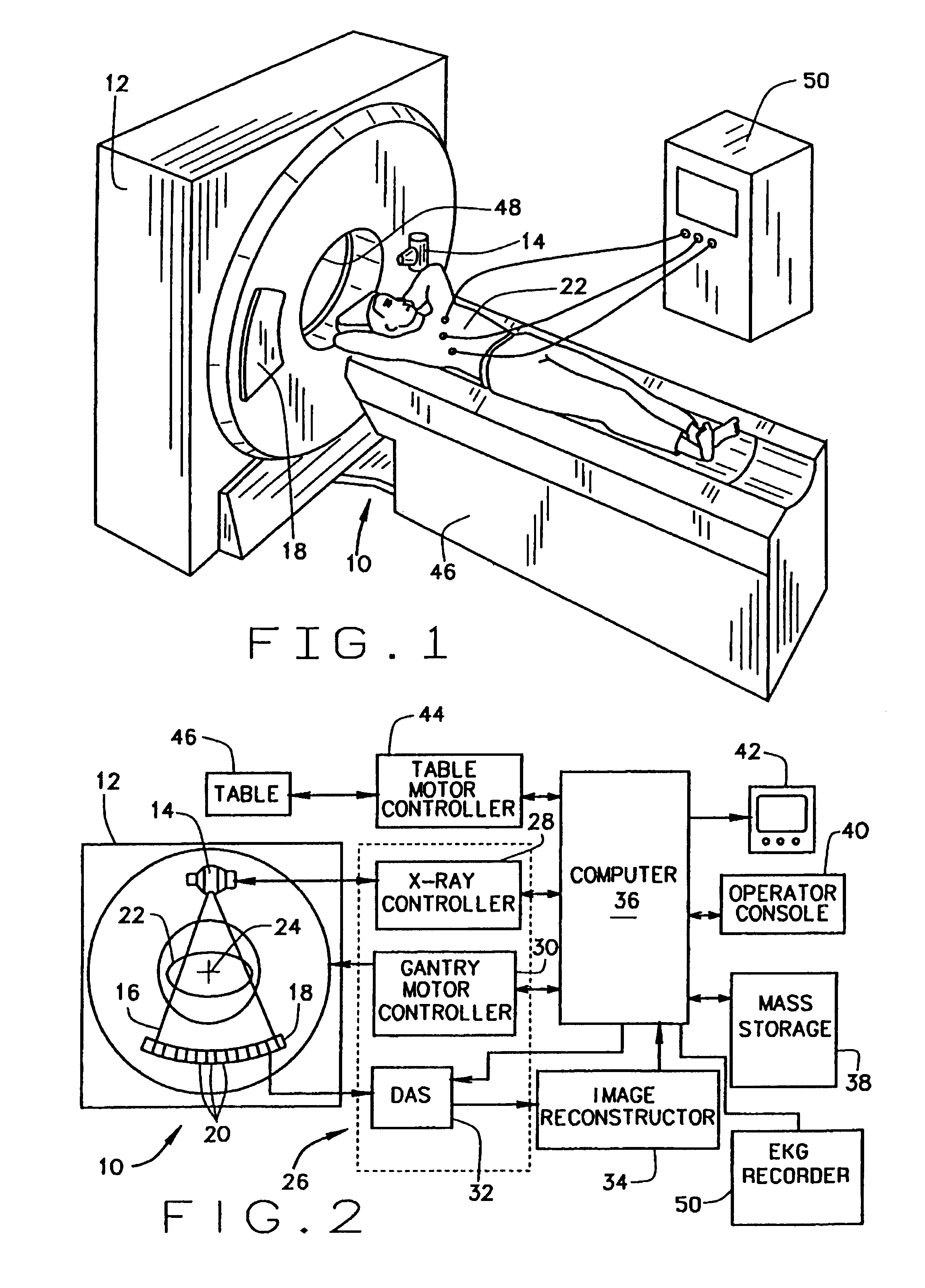
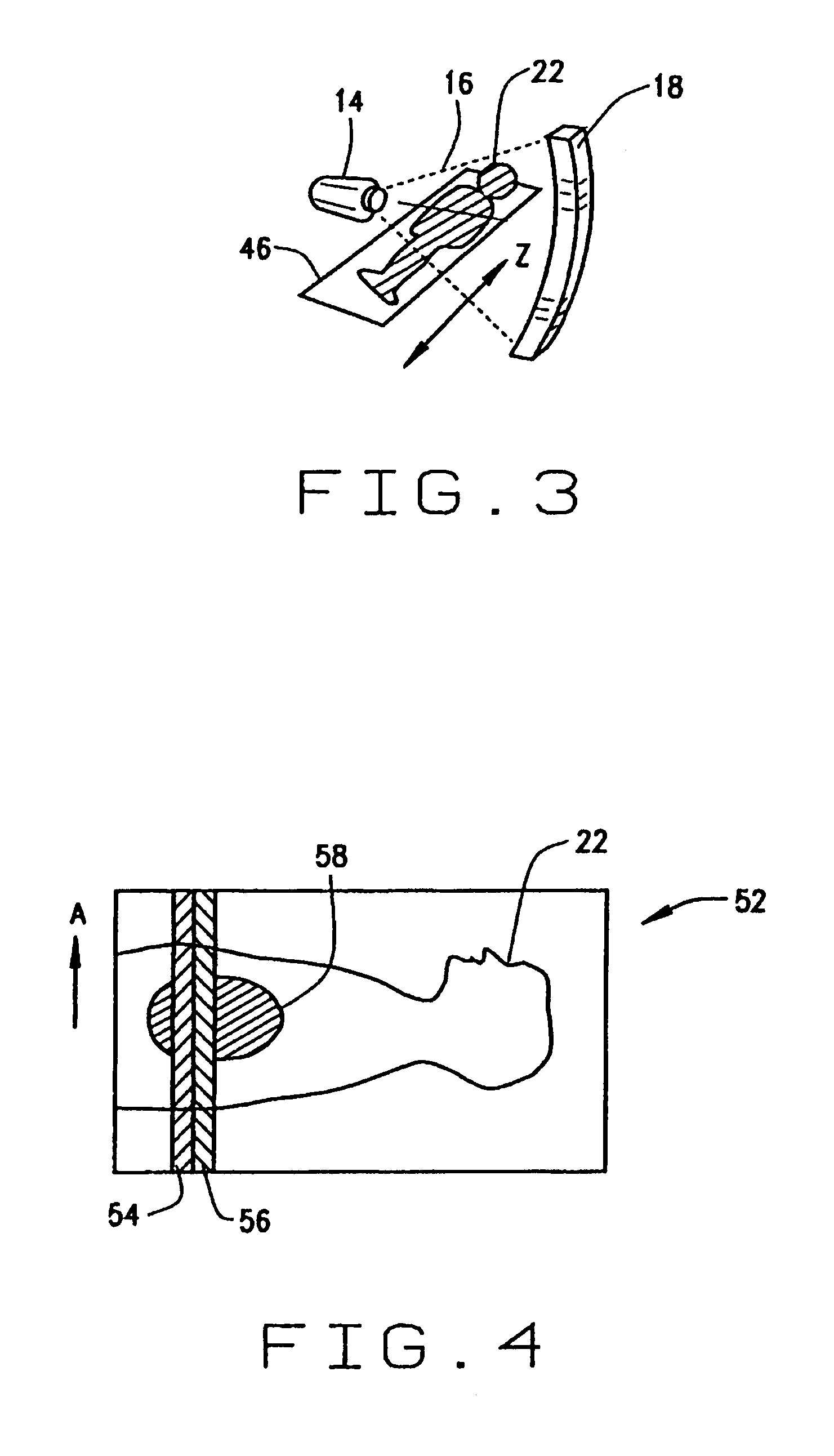
[0018]Referring to FIGS. 1 and 2, a computed tomography (CT) imaging system 10 is shown as including a gantry 12 representative of a “third generation” CT scanner. Gantry 12 has an x-ray source 14 that projects a beam of x-rays 16 toward a detector array 18 on the opposite side of gantry 12. Detector array 18 is formed by detector elements 20 which together sense the projected x-rays that pass through an object 22, for example a medical patient. Detector array 18 may be fabricated in a single slice or multi-slice configuration. Each detector element 20 produces an electrical signal that represents the intensity of an impinging x-ray beam and hence the attenuation of the beam as it passes through patient 22. During a scan to acquire x-ray projection data, gantry 12 and the components mounted thereon rotate about a center of rotation 24.

[0019]Rotation of gantry 12 and the operation of x-ray source 14 are governed by a control mechanism 26 of CT system 10. Control mechanism 26 includes...


PUM


Abstract

In one aspect, the present invention is a method for producing CT images of a patient's heart suitable for calcification scoring, in which the heart has a cardiac cycle. The method includes steps of acquiring data representative of a first scout-scanned CT image of physical locations of the patient's body including at least a portion of the patient's heart at phases φ1(L) of the cardiac cycle, acquiring data representative of a second scout-scanned CT image of the physical locations of the patient's body including at least a portion of the patient's heart at phases φ2(L) of the cardiac cycle different from φ1(L) at physical positions L of interest, and determining a difference image from the acquired data representative of the first scout-scanned CT image and the acquired data representative of the second scout-scanned CT image data. It is not necessary that φ1(L) and φ2(L) be constant as a function of position L.

Description

BACKGROUND OF THE INVENTION[0001]This invention relates generally to methods and apparatus for cardiac CT imaging, and more particularly to methods and apparatus that minimize an impact of heart motion in collecting calcification data from coronary images.[0002]In at least one known computed tomography (CT) imaging system configuration, an x-ray source projects a fan-shaped beam which is collimated to lie within an X-Y plane of a Cartesian coordinate system and generally referred to as the “imaging plane”. The x-ray beam passes through the object being imaged, such as a patient. The beam, after being attenuated by the object, impinges upon an array of radiation detectors. The intensity of the attenuated beam radiation received at the detector array is dependent upon the attenuation of the x-ray beam by the object. Each detector element of the array produces a separate electrical signal that is a measurement of the beam attenuation at the detector location. The attenuation measuremen...

Claims


Application Information

Patent Timeline
IPC IPC(8): H05G1/62G01N23/083A61B6/03
CPCA61B6/032A61B6/488A61B6/503A61B6/541
Inventor HSIEH, JIANGWOODFORD, MARK EDWARD
Owner GENERAL ELECTRIC CO
Why Eureka
Try Eureka