Dose setting limiter

a technology of limiter and dose, which is applied in the field of injection devices, can solve the problems of inability to set a dose that exceeds the amount of medicament left in the cartridge, and the distance can be very shor

Inactive Publication Date: 2010-11-23
NOVO NORDISK AS
View PDF175 Cites 49 Cited by
  • Summary
  • Abstract
  • Description
  • Claims
  • Application Information

AI Technical Summary

Benefits of technology

[0008]An object of the invention is to provide a limiting mechanism which prevents setting of a dose that exceeds the amount of liquid left in a cartridge of an injection device of the geared type wherein a dose is set by rotating a dose setting member relative to a driver and away from a fixed stop in the injection device, and the dose is injected by rotating back the dose setting member which during this rotation carries the driver element with it to rotate this driver element which moves the piston rod forward.
[0009]Such a mechanism is according to the invention characterized in that the driver element is provided with a track having a length which is related to the total amount of medicament in the cartridge and which track is engaged by a track follower coupled to the dose setting member to follow rotation of said dose setting member. During the setting of a dose the track follower will be advanced in the track of the driver to a position depending on the set dose as during dose setting the dose setting member and the driver are rotated relative to each other. As during the injection the driver follows the rotation of the dose setting member, the pin of the dose setting member will keep its position in the track of the driver when the set dose is injected. The length of the track is so adapted that the pin reaches the end of the track and makes an increase of the set dose impossible when a dose is set which corresponds to the amount of liquid remaining in the cartridge.

Problems solved by technology

When a dose is set it is convenient if a limiting device is provided which makes it impossible to set a dose that exceeds the amount of medicament which is left in the cartridge.
Especially by larger cartridges with a large cross section diameter this distance can be very short.

Method used


Image

  • Dose setting limiter
  • Dose setting limiter
  • Dose setting limiter

Examples


Embodiment Construction

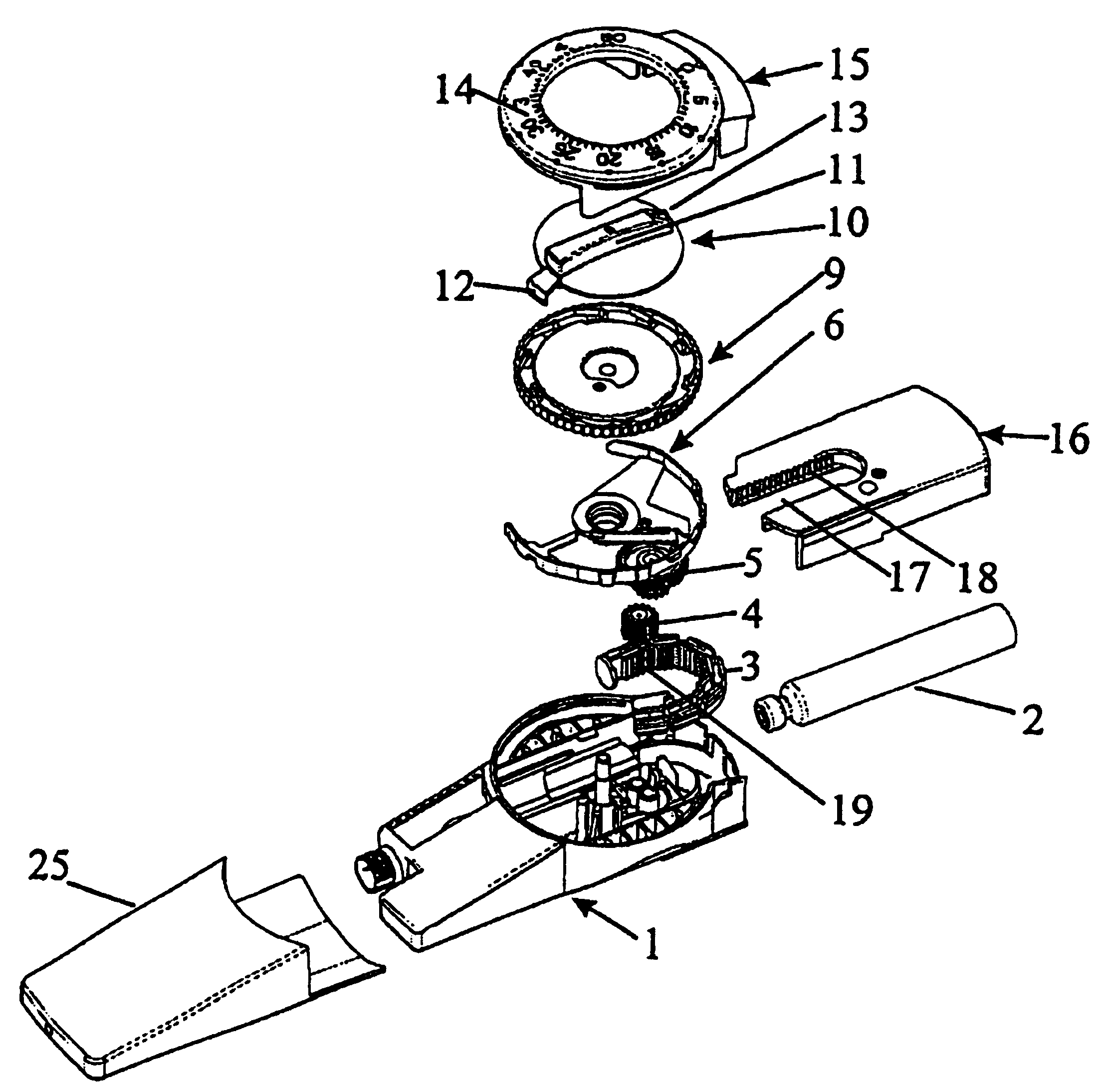
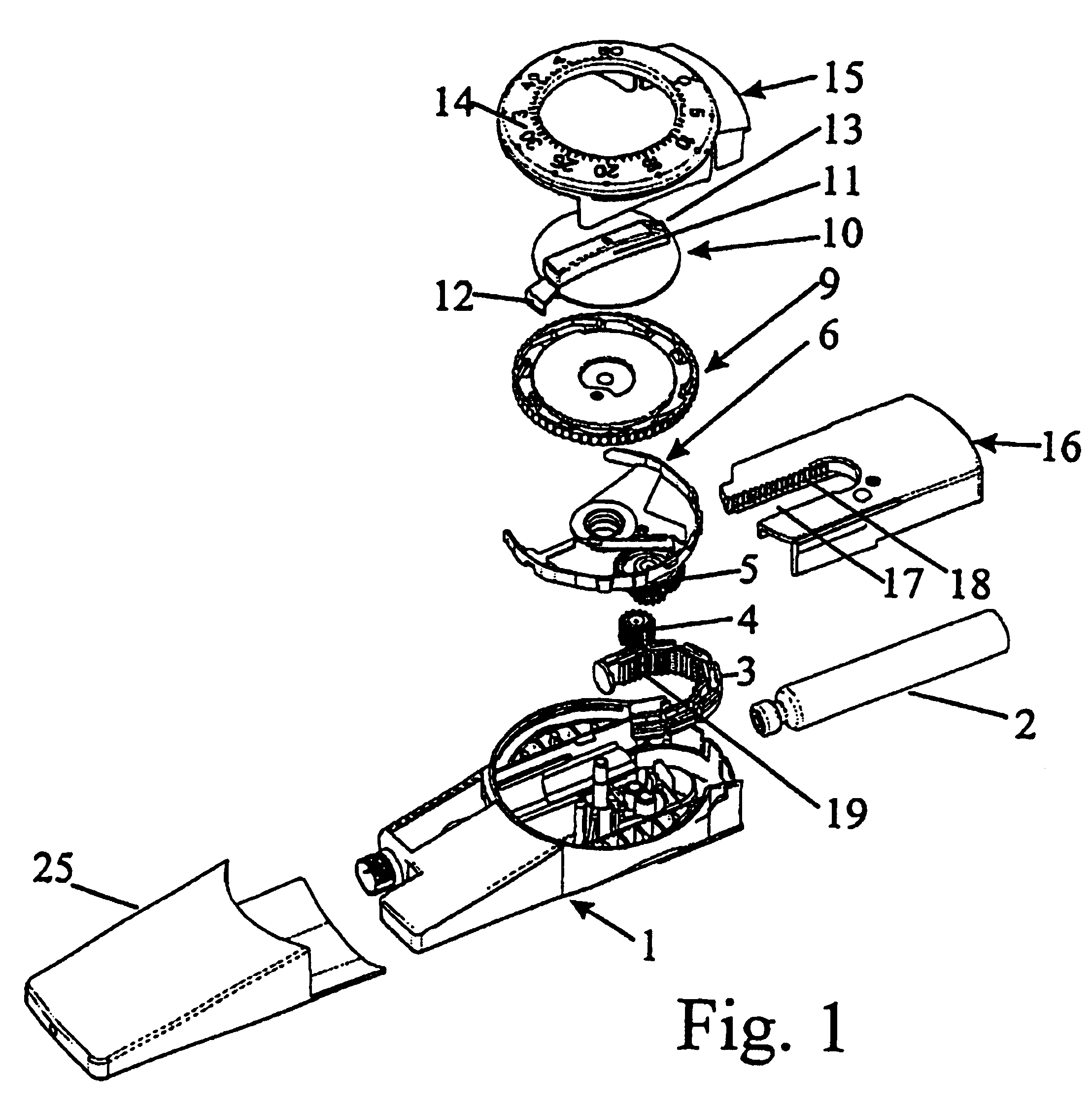
[0017]The syringe in FIG. 1 comprises a housing 1 accommodating a cartridge 2 from which the content can be pressed out by a piston rod 3 which is by injection via gear wheels 4 and 5 advanced a distance corresponding to a dose set by dose setting. A dose setting member 6 is provided with a toothed wheel 7 surrounding a central bore through which a pinion 8 on a driver 9 projects as it is shown in FIG. 2. The dose setting element 6 is operated through an operation element 10 which has a finger grip 11, a carrier 12 which engages the dose setting member 6, and a arrow 13 pointing on a scale 14 provided on a lid 15 which forms a part of the housing 1. FIG. 1 further shows a cap 25 which can be put on to protect a not shown needle which may be mounted on the syringe, and an injection button 16 which is sliding mounted in the housing 1 and which has a recess 17 which is on one of its side surfaces provided with a cogging 18.

[0018]In the assembled syringe the toothed wheel 7 on the dose ...


PUM


Abstract

A limiting mechanism which prevents the setting of a dose, which exceeds the amount of liquid left in a cartridge of an injection device, is disclosed. The injection device is the type where a dose is set by rotating a dose setting member relative to a driver and away from a fixed stop in the injection device. The dose setting member interfaces the driver such that the dose setting member can be rotated in one direction without rotating the driver. The dose is injected by rotating back the dose setting member which during the backward rotation carries the driver with it. Rotating the driver causes the piston rod to move forward inside the cartridge and expel some of the liquid contained in the cartridge. The driver is provided with a track having a length which is related to the total amount of liquid in the cartridge and which track is engaged by a track follower coupled to the dose setting member to follow rotation of this dose setting member. Each time a dose is set and injected, the track follower moves further into the track. When the track follower reaches the end of the track the dose setting member can not be rotated further, and a dose larger than the remaining liquid in the cartridge cannot be set.

Description

CROSS-REFERENCE TO RELATED APPLICATIONS[0001]This application is a reissue of U.S. Pat. No 6,582,404, which claims priority under 35 U.S.C. 119 of U.S. provisional application No. 60 / 155,612 filed on Sep. 23, 1999 and Danish application no. PA 1999 01309 filed on Sep. 16, 1999, the contents of which are fully incorporated herein by reference.FIELD OF THE INVENTION[0002]The present invention relates to injection devices wherein the contents of a cartridge are injected as a number of individually set doses.[0003]Such devices have a dose setting mechanism by which the doses are set for subsequent injecting when an injection button is operated. This can be obtained by moving a carrier along a piston rod a distance proportional to the wanted dose and subsequently moving the carrier back to its original position so that the carrier carries the piston rod with it instead of being moved along said piston rod.SCOPE OF THE RELATED ART[0004]From EP 327 910 is known a syringe by which a dose is...

Claims


Application Information

Patent Timeline
Patent Type & Authority Patents(United States)
IPC IPC(8): A61M5/00A61M5/315A61M5/178A61M5/175A61M5/24A61M5/31G01F11/06
CPCA61M5/24A61M5/31511A61M5/31525A61M5/31535A61M5/31541A61M5/31551A61M5/31553A61M5/31555A61M5/31568A61M5/31575A61M5/3158A61M5/31585A61M2005/3125A61M2005/3126A61M2005/31518A61M2005/3152A61M5/315A61M5/168
Inventor KLITGAARD, PETER CHRISTIANHANSEN, STEFFENRADMER, BOMOLLER, CLAUS SCHMIDT
Owner NOVO NORDISK AS
Why Eureka
Try Eureka