
Image scanner using low-pixel-density CCD to achieve high-pixel-density scanning quality by pixel-level shift of CCD

Inactive Publication Date: 2012-01-10
INTELLECTUAL VENTURES ASSETS 191 LLC
View PDF4 Cites 0 Cited by
  • Summary
  • Abstract
  • Description
  • Claims
  • Application Information

AI Technical Summary

Benefits of technology

[0006]Therefore, an object of the present invention is to provide an image scanner using a low-pixel-density CCD, which is moved in a pixel level, to achieve a high-pixel-density scanning quality in an efficient way.

Problems solved by technology

If a CCD of a high pixel number is used, the cost of the resulting image scanner will multiply increase.
This process, however, still has disadvantages.
First of all, the long distance movement of the light-program device including the CCD and the lens device across a half of the document along the X-direction has adversely effect on positioning precision.
In addition, the switching device for driving the light-program device to move that long requires a complicated and bulky structure, and thus consumes a lot of power.
Further, it takes time to move such a long distance.

Method used


Image

  • Image scanner using low-pixel-density CCD to achieve high-pixel-density scanning quality by pixel-level shift of CCD
  • Image scanner using low-pixel-density CCD to achieve high-pixel-density scanning quality by pixel-level shift of CCD
  • Image scanner using low-pixel-density CCD to achieve high-pixel-density scanning quality by pixel-level shift of CCD

Examples


Embodiment Construction

[0025]The present invention will now be described more specifically with reference to the following embodiments. It is to be noted that the following descriptions of preferred embodiments of this invention are presented herein for purpose of illustration and description only; it is not intended to be exhaustive or to be limited to the precise form disclosed.

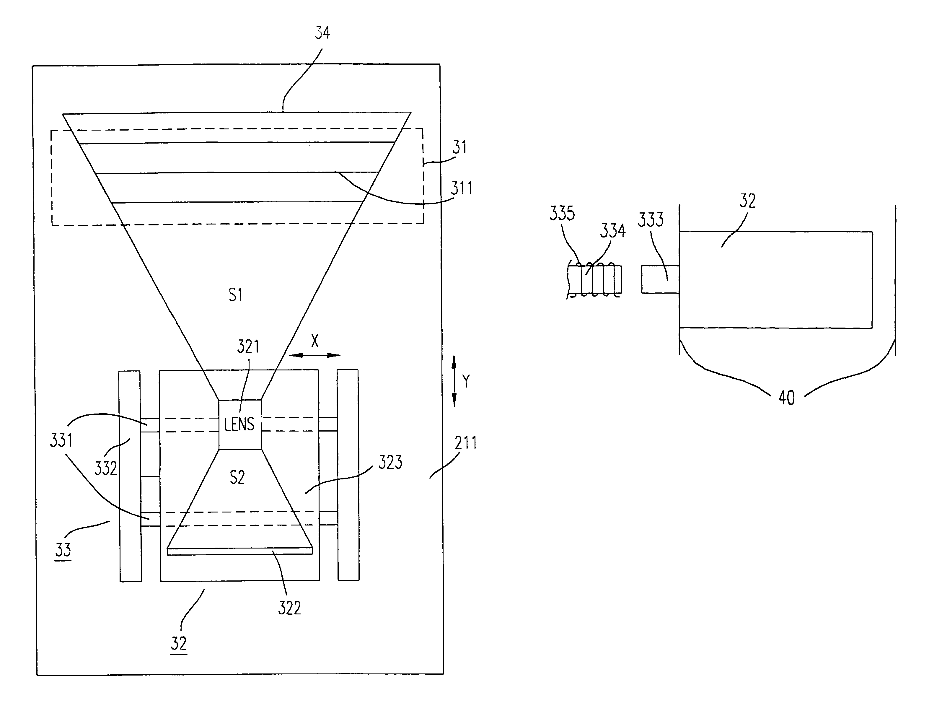
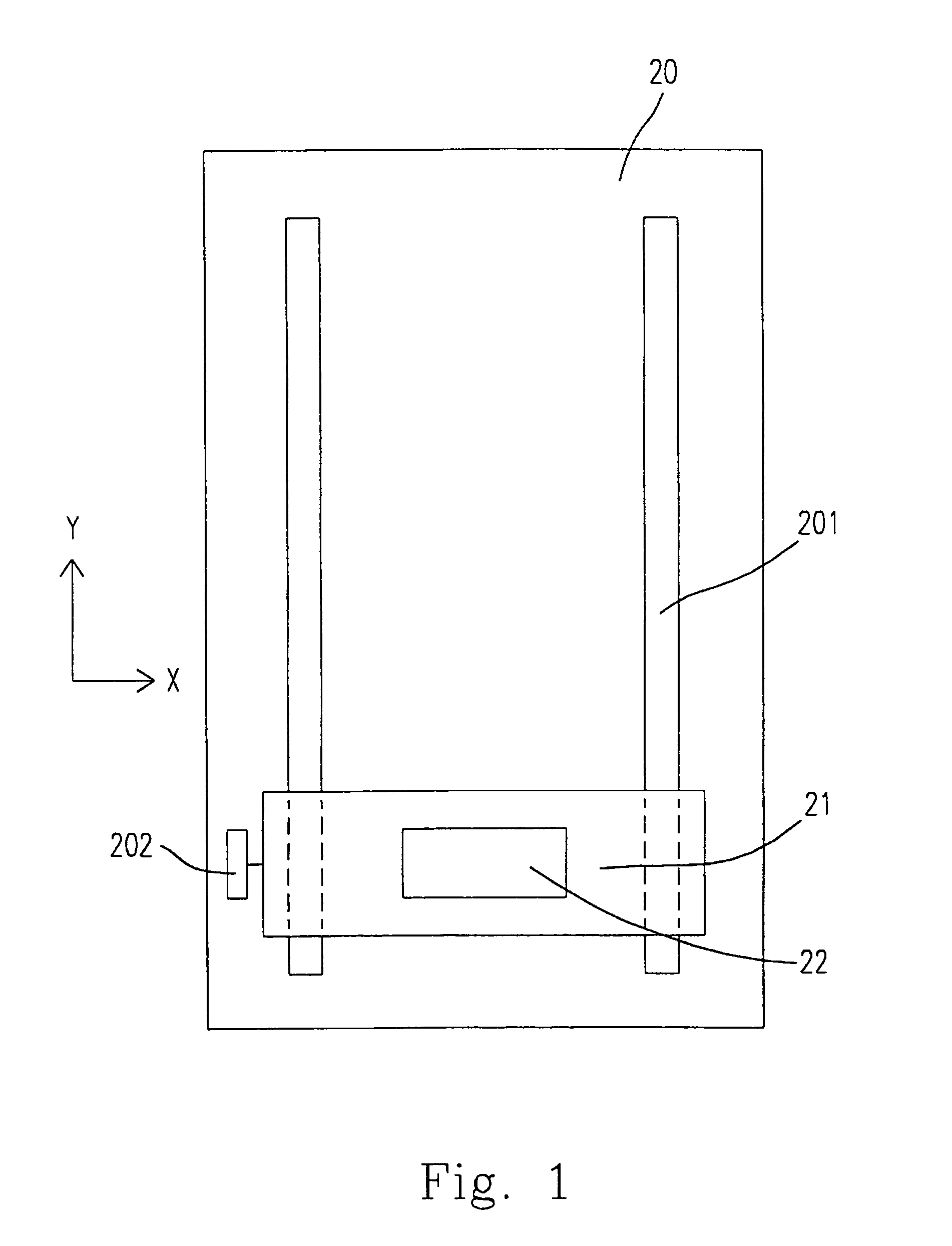
[0026]Please refer to FIG. 1 which is a schematic diagram partially showing a preferred embodiment of an image scanner according to the present invention. The image scanner 20 includes a carriage 21 for accommodating therein an optical device 22 for picking up the image of a scanned object (not shown). The carriage 21 is moved by a stepping motor 202 along a pair of guiding shafts 201 in a Y-direction. For each step, the optical device 22 is actuated to pick up a scan line of the image of an object in an X-direction. With the movement of the carriage 21 along the Y-direction, the entire object is scanned line by line.

[0027]The op...


PUM


Abstract

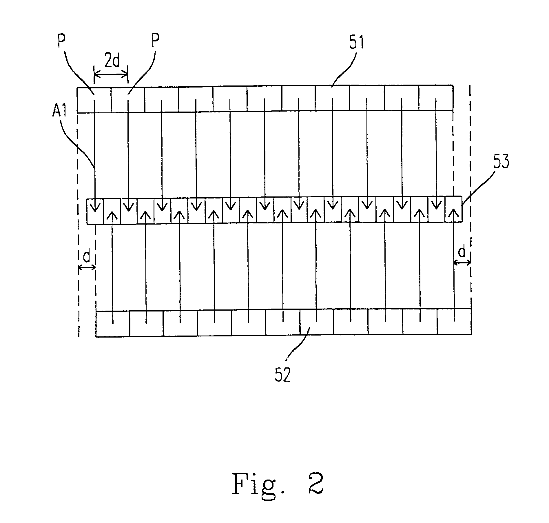
An image scanner performing multiple scanning operations for a single scan line is disclosed. The additional scanning operations are performed between two adjacent pixels. For a double scanning mode, the CCD performs one scanning operation for a scan line at a first position. Then, the CCD is moved from the first position to a second position along the X-direction to perform the other scanning operation at the second position. The distance between the first and the second positions is a half of the distance between two adjacent pixels. The scanning data of the two scanning operations are alternatively arranged and converted into final image data. By this way, a low-pixel-density CCD can be used to obtain a high-pixel-density scanning quality.

Description

FIELD OF THE INVENTION[0001]The present invention relates to an image scanner which includes a charge coupled device (CCD) of a low pixel density, and particularly to an image scanner using the low-pixel-density CCD to achieve a better scanning quality than it could. The better scanning quality can be obtained by performing a small-amount shift of the CCD.BACKGROUND OF THE INVENTION[0002]Due to the improvement on manufacturing techniques and the reduction of cost, an image scanner becomes a popular peripheral equipment for a personal computer. Meanwhile, owing to the enhancement of the processing speed of the computer itself and the increasing requirement of users on the scanning quality, the resolution of an image scanner is getting higher and higher. Therefore, it is a trend for the manufacturers of image scanners to improve the resolution as possible as they can.[0003]The resolution of an image scanner is generally expressed by X DPI×Y DPI wherein DPI means Dot Per Inch. the numb...

Claims


Application Information

Patent Timeline
IPC IPC(8): H04N1/04H04N1/10H04N1/192
CPCH04N1/1013H04N1/192
Inventor TSAI, JENN-TSAIRCHEN, JONE-NUNLU, I-CHANG
Owner INTELLECTUAL VENTURES ASSETS 191 LLC
Learn More