Method and device for measuring the geometry of a cutting edge to be chamfered

Inactive Publication Date: 2009-06-18
ROLLOMATIC
View PDF27 Cites 0 Cited by
  • Summary
  • Abstract
  • Description
  • Claims
  • Application Information

AI Technical Summary

Benefits of technology

[0004]The aim of the present invention is to propose a method more efficient than the means known up to no

Problems solved by technology

After machining, the cutting edge appears as a very finely sharpened line so that immediately from the start of use the risk of nicking is high, which constitutes a risk of early wear.
Moreover, as the cutting edge quickly becomes irregular, this is prejudicial to the quality of parts machined by these tools.
However, in practice, its actual shape differs substantially from the calculated theoretical curve, in particular owing to inaccuracies of the grinding operations on the sides of the threads of the tool.
This way of proceeding has however been revealed to be unsatisfactory through its lack of accuracy, due in particular to the errors generated by the probing blade itself and its movement, and by the complications it brings about.

Method used


Image

  • Method and device for measuring the geometry of a cutting edge to be chamfered
  • Method and device for measuring the geometry of a cutting edge to be chamfered
  • Method and device for measuring the geometry of a cutting edge to be chamfered

Examples


Embodiment Construction

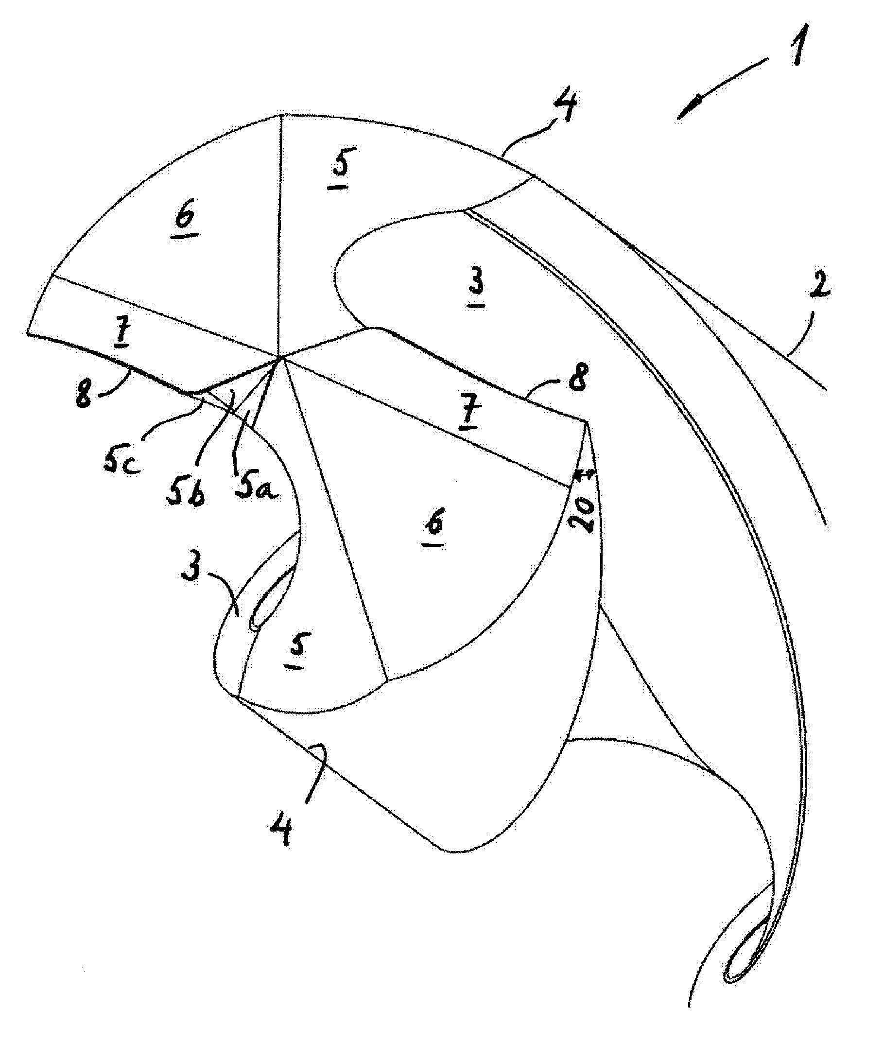
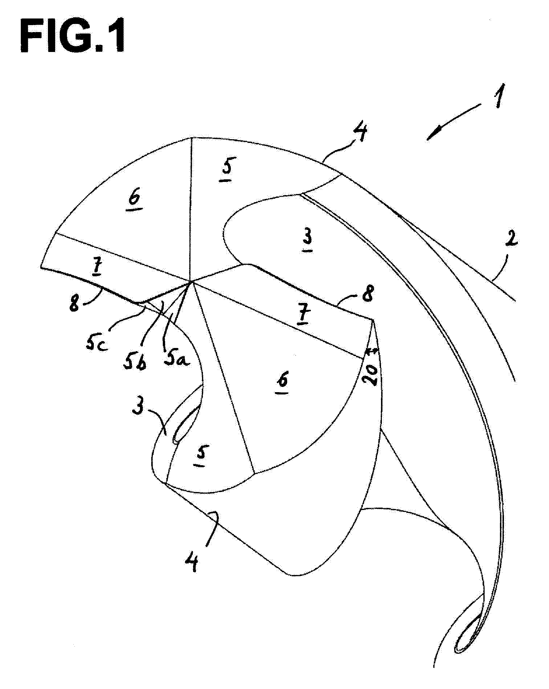
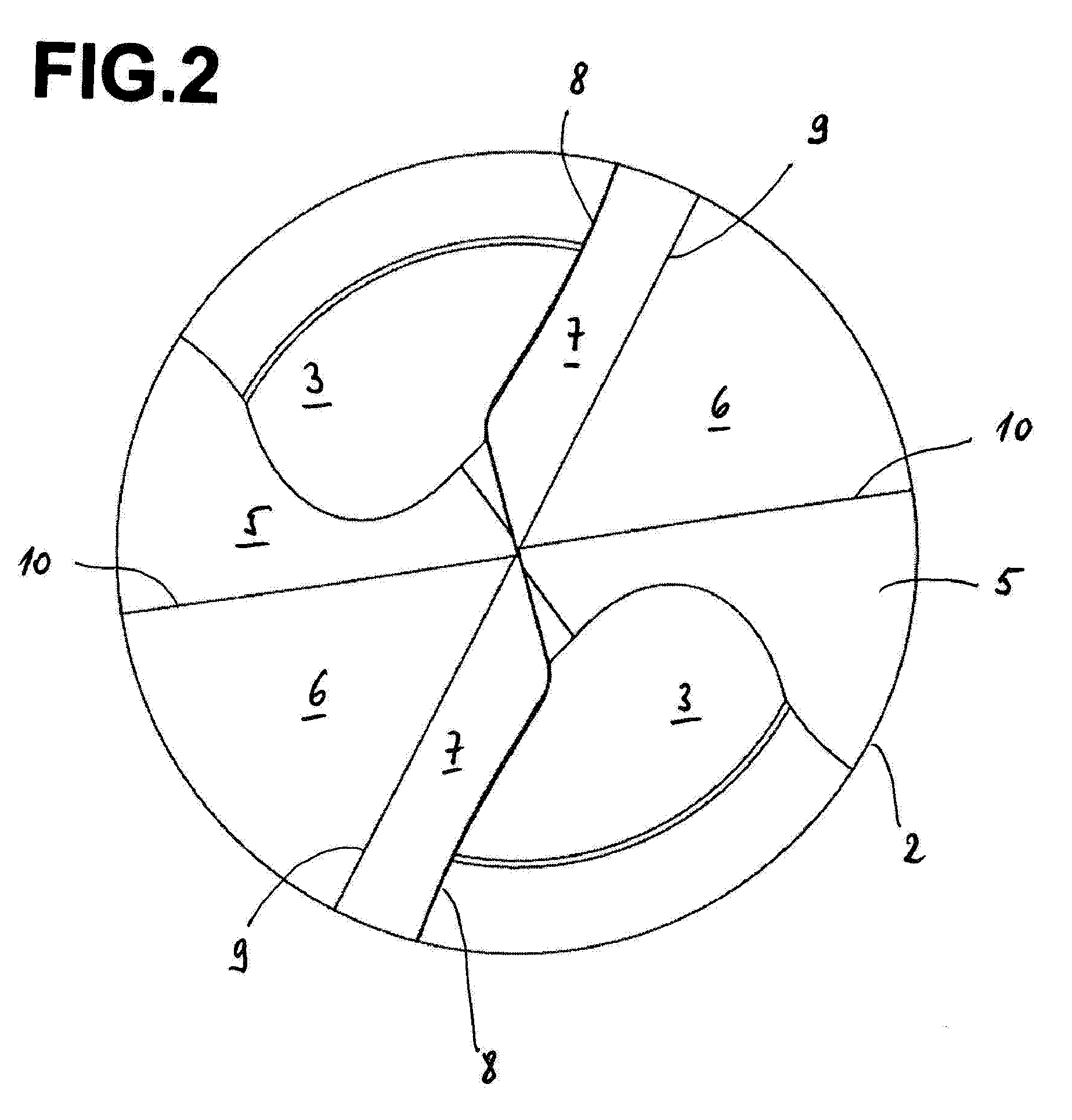
[0013]FIGS. 1 and 2 show details of the shape of a drill 1, intended for example for drilling tough steels. It has a cylindrical lateral face 2 in which there are made two diametrically opposite helical grooves 3, extending to the active end of the tool. These grooves determine between them two threads 4 whereof the width in the axial direction is constant as far as the vicinity of the active end of the tool, but decreases in stages on approaching the tip through the presence of three successive ramps 5, 6, 7 made on the rear side of the threads 4. The last ramp 7 joins the front side of the thread along a three-dimensional edge line 8 described in detail later. The slopes and lengths of the ramps 5, 6, 7 are determined according to the performance desired for the drill. In fact as can be seen in FIG. 2, the two edges 9 that separate each ramp 7 from the adjacent ramp 6 are straight, diametrically opposite and determine in the diametral plane of the drill an obtuse angle characteris...


PUM

PropertyMeasurementUnit
Angleaaaaaaaaaa
Proximity effectaaaaaaaaaa

Abstract

The machining of drills (1) includes an operation for chamfering the cutting edges (8) performed in two steps. In the first step the rotating grindstone (15) is directed to various locations of the cutting edge (8) and the point of contact is detected by an electronic appliance (17) whereof the electronic module (19) controls the stoppage of the grindstone, its return to the starting position and the recording of the position of the grindstone at the time of contact. In the second step the grindstone (15) is controlled to follow the left line obtained by connecting the points registered during the first step.

Description

STATE OF THE ART[0001]Cutting tools such as drills, endmills, in particular ballnose endmills, certain chisels, etc. must satisfy ever increasing requirements as regards their performance in terms of accuracy, cutting quality, speed and durability. In certain cases, in particular those of drills, the cutting edge extends along a curve defined in space by the junction of two surfaces forming between them a fairly acute dihedral angle. These tools are generally machined by grinding on CNC machines. After machining, the cutting edge appears as a very finely sharpened line so that immediately from the start of use the risk of nicking is high, which constitutes a risk of early wear. Moreover, as the cutting edge quickly becomes irregular, this is prejudicial to the quality of parts machined by these tools. This is why it is common to regrind the end of the cutting edge by grinding a protective chamfer.[0002]In the case of drills in particular, the cutting edge is a three-dimensional curv...

Claims


Application Information

Patent Timeline
IPC IPC(8): G05B19/401G05B19/19
CPCB23Q17/2233B24B3/26Y10T29/511Y10T409/101113Y10T409/50246B24B47/22Y10T83/0259
Inventor FRITSCHY, PATRICK
Owner ROLLOMATIC
Why Eureka
Try Eureka