Roller bearing

Inactive Publication Date: 2021-06-08
NSK LTD
View PDF17 Cites 0 Cited by
  • Summary
  • Abstract
  • Description
  • Claims
  • Application Information

AI Technical Summary

Benefits of technology

[0009]According to the above aspects of the present invention, the end face (roller guide surface) of the collar portion on its sliding contact side with the roller is generally formed open at a certain angle with respect to a surface perpendicular to the raceway surface of the ring in order to facilitate the introduction of lubricating oil into between the roller and the roller guide surface of the collar portion. Therefore, a point of intersection with a grinding relief portion formed in the roller guide surface of the collar portion is geometrically easiest to touch the end face of the roller. On the other hand, since the contact side of the roller end face to be slidingly contacted with the collar portion is formed at right angles to the outside diameter surface of the roller, a point of intersection between a connecting portion (chamfer portion), which connects the outside diameter surface of the roller with the end face of the roller, and the end face of the roller is geometrically easiest to touch the collar portion.
[0010]Also, since lubricating oil existing in a portion, where the end face of the roller and collar portion is contacted with each other, is pulled into a small clearance between them due to the viscosity thereof, the shape of the mutual contact portion between the roller end face and collar portion may preferably be formed to have a clearance before and behind the mutual contact portion. Especially, because the shape of the end face of the roller is formed as a continuously curved shape, there is eliminated the possibility that an oil film can be cut due to high surface pressure occurring locally in the mutual contact portion, thereby being able to produce the oil film positively. Thanks

Problems solved by technology

In the roller bearing of this type, in case where the ring is rotated at a high speed, there is generated frictional heat between the collar portion and roller, thereby raising a possibility that seizure can occur in the collar portion and roller.
However, in both of the above-mentioned conventional roller bearings, the end face of the roller an

Method used


Image

  • Roller bearing
  • Roller bearing
  • Roller bearing

Examples


Example

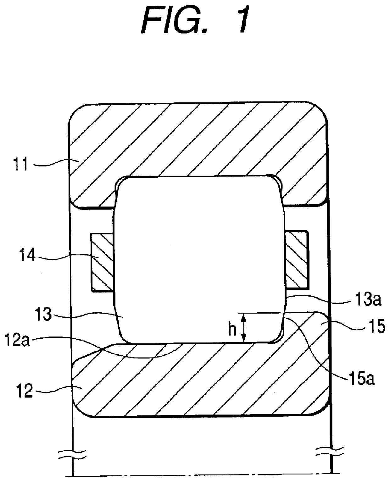
[0024]FIG. 1 shows a partial section view of a first embodiment of a roller bearing according to the present invention. As shown in FIG. 1, a roller bearing according to the present embodiment comprises an outer ring 11, an inner ring 12, a cylindrical roller 13 and a retainer 14; and, in the right (in FIG. 1) end portion of the inner ring 12, there is formed a collar portion 15. The collar portion 15 is used to guide the cylindrical roller 13 in the circumferential direction of the outer ring 11 and inner ring 12. In case where the diameter of the cylindrical roller 13 is 2R (=19 mm), the height h from the raceway surface 12a of the inner ring 12 to the leading end of the collar portion 15 is set such that h=approx. 0.38R (3.65 mm). Also, the collar portion 15 has a roller guide surface 15a extending almost at right angles to the raceway surface 12a of the inner ring 12. The cylindrical roller 13 is structured such that, while its end face 13a is slidingly contacted with the roller...

Example

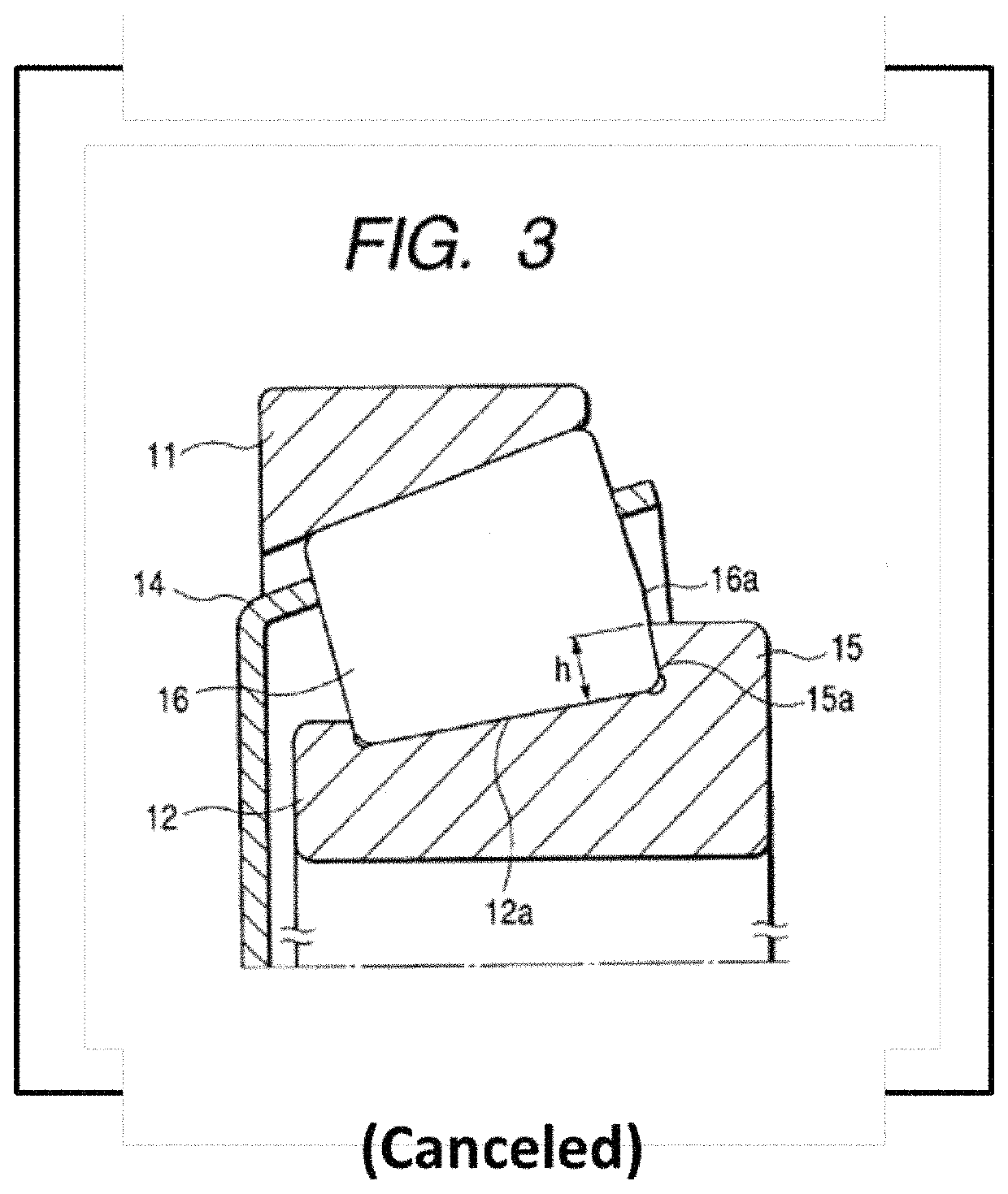
[0026]Next, FIG. 3 shows a partial section view of a second embodiment of a roller bearing according to the present invention. As shown in FIG. 3, a roller bearing according to the present embodiment comprises an outer ring 11, an inner ring 12, a conical roller 16 and a retainer 14; and, in the right (in FIG. 3) end portion of the inner ring 12, there is formed a collar portion 15. The collar portion 15 is used to guide the cylindrical roller 13 in the circumferential direction of the outer ring 11 and inner ring 12. In case where the maximum diameter of the conical roller 16 is 2R, the height h from the raceway surface 12a of the inner ring 12 to the leading end of the collar portion 15 is set such that h=approx. 0.6R. Also, the collar portion 15 has a roller guide surface 15a extending almost at right angles to the raceway surface 12a of the inner ring 12. The conical roller 16 is structured such that, while its end face 16a is slidingly contacted with the roller guide surface 15...


PUM


Abstract

The contact portion of the end face of a conical roller, which is a portion to be slidingly contacted with a collar portion, is ground such that the outer contour line of the section thereof has a continuously curved line which passes through at least not only the first point but also between the third position and fourth position.

Description

[0001]The present invention relates to a roller bearing such as a conical roller bearing and a cylindrical roller bearing and, in particular, to a roller bearing in which a collar portion for guiding a plurality of rollers in the circumferential direction of a ring is formed in the end portion of the ring.[0002]Generally, in most of roller bearings such as a conical roller bearing and a cylindrical roller bearing, a collar portion for guiding a plurality of rollers in the circumferential direction of a ring is formed in the end portion of the ring, and the end face of the roller is slidingly contacted with the collar portion. In the roller bearing of this type, in case where the ring is rotated at a high speed, there is generated frictional heat between the collar portion and roller, thereby raising a possibility that seizure can occur in the collar portion and roller. Thus, it is necessary to reduce the frictional heat that is generated between the collar portion and roller. In vie...

Claims


Application Information

Patent Timeline
IPC IPC(8): F16C33/36F16C23/08F16C19/22F16C33/34F16C33/58F16C19/26F16C19/36
CPCF16C23/088F16C19/225F16C33/34F16C33/585F16C19/26F16C19/364F16C33/366F16C2300/02F16C2240/50
Inventor MURAI, TAKASHITSUNASHIMA, SHINICHIFUJII, OSAMU
Owner NSK LTD
Why Eureka
Try Eureka