Brake controller

A control device and brake technology, applied in the direction of brakes, etc., can solve the problems of divergence, control confusion of braking amount, and large control delay.

Inactive Publication Date: 2007-09-26
TOYOTA JIDOSHA KK
View PDF7 Cites 0 Cited by
  • Summary
  • Abstract
  • Description
  • Claims
  • Application Information

AI Technical Summary

Problems solved by technology

[0004] In the braking system described in Patent Document 1, the brake control device obtains the requested braking amount requested by the driver based on the operating state of the brake operating member, and determines the target braking amount based on the obtained requested braking amount. However, if the target braking amount is determined in this way, even if it changes sensitively in respo...

Method used


Image

  • Brake controller
  • Brake controller
  • Brake controller

Examples


Embodiment Construction

[0097] Hereinafter, embodiments of the claimable invention will be described with reference to the drawings. In addition, in addition to the following embodiments, the claimable invention can also be implemented in a manner mainly based on the method described in the item of the above-mentioned "Invention Mode", and various modifications are made based on the knowledge of those skilled in the art.

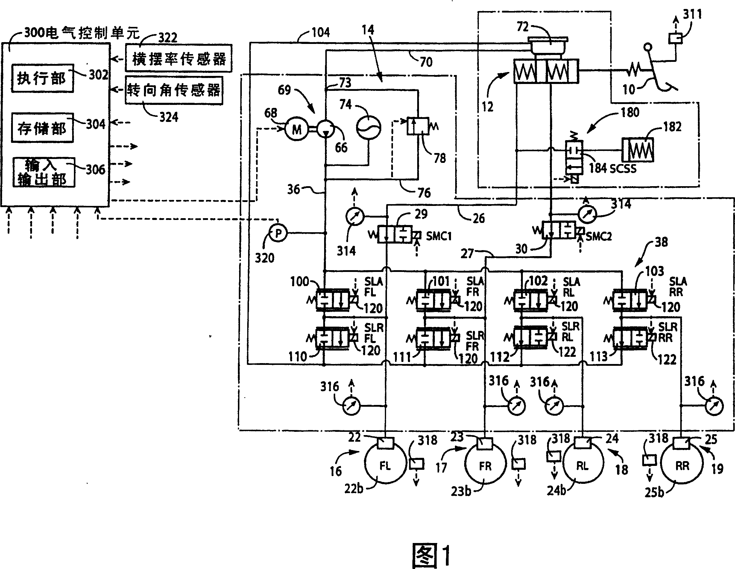
[0098] FIG. 1 shows a brake system for a vehicle having a brake control device as an embodiment. The brake system includes: a brake pedal 10 as a brake operating component, a master cylinder 12 including two pressurizing chambers, a power hydraulic source 14 driven by power, and hydraulic brakes 16 respectively arranged on the front, rear, left, and right wheels. -19.

[0099] The hydraulic brakes 16-19 respectively have brake cylinders 22-25 and are driven by the hydraulic pressure of the brake cylinders 22-25. In this embodiment, it is a disc brake in which friction material held on ...


PUM


Abstract

To provide a brake control device capable of excellently avoiding the control delay when the increase gradient of the required braking amount is large, and the control disturbance when the increase gradient of the required braking amount is small. The temporary target hydraulic pressure Prefa is determined (S3) based on the required deceleration Greft (S1). The corrected target hydraulic pressure Prefb is determined (S4) by limiting the gradient of the temporary target hydraulic pressure Prefa to be the first limit gradient L1. If the temporary target hydraulic pressure difference Delta Pref of the corrected target hydraulic pressure Prefb subtracted from the temporary target hydraulic pressure Prefa is not a more than a set value (S5, S6), the corrected target hydraulic pressure Prefb is determined to be the target hydraulic pressure Prefc (S7). Otherwise, the limit gradient is changed to be the second limit gradient L2 and the target hydraulic pressure Prefc is operated (S8).

Description

Technical field [0001] The present invention relates to a device for controlling the brakes of a braked vehicle, and more specifically, to an improvement in the control performance of the brake control device. Background technique [0002] Most of the braking systems of braking vehicles are equipped with a brake control device that, when increasing the amount of braking, determines the target braking amount of the wheels based on the amount of braking that should be applied to the wheels, that is, the requested braking amount , And control to make the actual braking amount, that is, the actual braking amount close to the target braking amount. An example of this is described in Patent Document 1 below. The brake system includes: a brake pedal as a brake operating component, a stroke sensor that detects the operating stroke of the brake pedal, a master pressure sensor that detects the hydraulic pressure of the master cylinder corresponding to the operating force of the brake pedal...

Claims


Application Information

Patent Timeline
IPC IPC(8): B60T8/58
Inventor 宫崎徹也
Owner TOYOTA JIDOSHA KK
Why Eureka
Try Eureka