Boiler, marine steam turbine propulsion system with the boiler, ship with the propulsion system, and boiler control method

A steam turbine and steam technology, applied in boilers, marine steam turbine propulsion systems with the boilers, ships with the propulsion systems, and boiler control fields, can solve control delays, main steam temperature, pressure instability, and long steam paths and other issues to achieve the effect of avoiding control delay

Active Publication Date: 2020-01-21
MITSUBISHI HEAVY IND LTD
View PDF2 Cites 0 Cited by
  • Summary
  • Abstract
  • Description
  • Claims
  • Application Information

AI Technical Summary

Problems solved by technology

However, even with such a structure, since the superheater is composed of the primary superheater and the secondary superheater, it becomes a long steam path. Therefore, there is a concern that the temperature of the main steam at the outlet of the superheater is obtained and fed back as described above. Control delay occurs during control, the temperature and pressure of the main steam become unstable, and the metal temperature of the heat transfer tube exceeds the allowable value due to this situation

Method used


Image

  • Boiler, marine steam turbine propulsion system with the boiler, ship with the propulsion system, and boiler control method
  • Boiler, marine steam turbine propulsion system with the boiler, ship with the propulsion system, and boiler control method
  • Boiler, marine steam turbine propulsion system with the boiler, ship with the propulsion system, and boiler control method

Examples


Embodiment Construction

[0098] Hereinafter, embodiments of the present invention will be described with reference to the drawings.

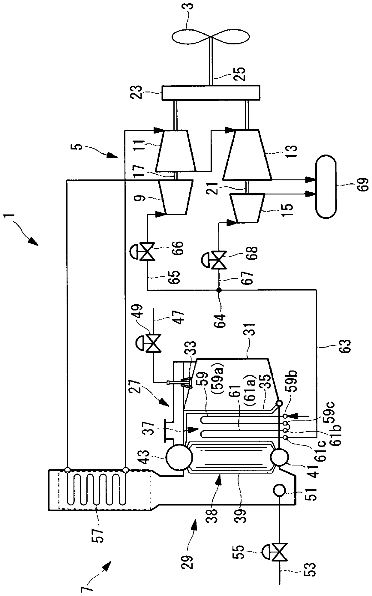
[0099] figure 1 The middle represents a marine steam turbine propulsion system 1 applied to a ship. The marine steam turbine propulsion system 1 has: a propulsion propeller (propeller) 3 that generates thrust in water; a steam turbine 5 that applies rotational force to the propeller 3 ; and a boiler 7 that supplies superheated steam as main steam to the steam turbine 5 .

[0100] The steam turbine 5 has a high-pressure turbine 9 , an intermediate-pressure turbine 11 , a low-pressure turbine 13 , and a backward turbine 15 . The high-pressure turbine 9 and the intermediate-pressure turbine 11 are connected via a common first rotating shaft 17 . The low-pressure turbine 13 and the reverse turbine 15 are connected via a common second rotating shaft 21 . The first rotating shaft 17 and the second rotating shaft 21 are arranged side by side, and their respective output end...


PUM


Abstract

The present invention is provided with: a steam introduction path (74a) which extracts steam from a steam extraction section (59e) at a midway position of a superheater (37); a steam return path (74b) which returns the steam to a stream return section (59f) of the superheater (37); a desuperheater (76) for reducing the temperature of the steam; a first steam flow rate adjustment valve (80) and a second steam flow rate adjustment valve (81) which adjust the flow rate of the steam flowing to the desuperheater (76); and a first temperature sensor (72) which is disposed further towards the downstream side of the flow of steam than the steam return section (59f) of the superheater (37), and which measures a first steam temperature (T1) at a midway position of the superheater (37). The present invention is also provided with superheater-outlet-temperature relationship information (R1) which determines the relationship between the superheater-outlet temperature (T2) and the first steam temperature (T1). The first steam flow rate adjustment valve (80) and the second steam flow rate adjustment valve (81) are controlled on the basis of the superheater-outlet-temperature relationship information (R1) and the measurement result of the first temperature sensor (72), such that the superheater-outlet temperature (T2) becomes a target value.

Description

technical field [0001] For example, the present invention relates to a boiler such as a marine boiler, a marine steam turbine propulsion system having the boiler, a ship having the marine steam turbine propulsion system, and a boiler control method. Background technique [0002] Boilers are used to supply the main steam required on the demand side such as steam turbines. Typically, a boiler has: a burner, which burns in the furnace; an evaporator, which is heated by the combustion gas produced by the burner to generate steam; and a superheater, in which the The steam guided by the boiler is superheated by the combustion gas to produce superheated steam. In addition, higher temperature and higher pressure main steam may be required for boilers in response to improvement in thermal efficiency on the demand side. For example, a marine reheat boiler having a reheater is used as a marine boiler that supplies main steam to a steam turbine that drives a propulsion propeller of a ...

Claims


Application Information

Patent Timeline
Patent Type & Authority Patents(China)
IPC IPC(8): F22G5/16F01D17/00F01D17/08F01D25/00F22G5/12
CPCF01D17/00F01D17/08F01D25/00F22G5/12F22G5/16
Inventor 中村龙太西山太郎
Owner MITSUBISHI HEAVY IND LTD
Why Eureka
Try Eureka