
Separate layer gas injection tube pile

A technique of pipe string and gas injection, which is applied in the direction of production fluid, wellbore/well components, earthwork drilling and production, etc., which can solve problems such as inability to layer injection, multiple processes, reduced strength and service life, etc., so as to avoid or Effects of alleviating corrosion, improving gas injection efficiency, and reducing operating costs

Inactive Publication Date: 2007-10-17
OIL EXTRACTION TECH INST OF SINOPEC SHENGLI OILFIELD
View PDF5 Cites 0 Cited by
  • Summary
  • Abstract
  • Description
  • Claims
  • Application Information

AI Technical Summary

Problems solved by technology

[0002] At present, the process strings used in gas injection in oilfields mostly adopt the structure of imported permanent packers and gas-tight tubing. The tool is corroded and damaged, which reduces its strength and service life; ② cannot be injected in layers, but can only be injected in general, and the gas injection effect is not good; Carrying out overhaul operations requires many procedures and high costs

Method used


Image

  • Separate layer gas injection tube pile
  • Separate layer gas injection tube pile

Examples


Embodiment Construction

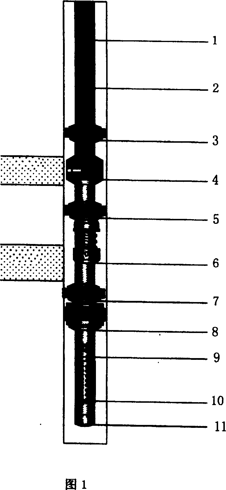
[0014] Referring to the accompanying drawings, a string for layered gas injection process includes outer pipe 1, inner pipe 2, packer with channel 3, balance packer 5, safety injection valve 6, well flushing packer 7, support card tile 8, circulation valve 9, screen pipe 10 and plug 11, and also includes a diversion check valve 4 connected between the channel packer 3 and the balance packer 5, and the outer pipe 1 is connected to the On the spacer 3, the inner pipe 2 passes through the channeled packer 3, and is installed in the diversion check valve 4. The balance packer 5 is connected with the safety injection valve 6, the well flushing packer 7, and the support in sequence. Slips 8, circulation valve 9, screen pipe 10 and plug 11.

[0015] The diversion check valve 4 comprises an upper joint 41 and a diverter seat 47 connected and installed on it, a lower joint 52, a seal 51, a piston 49, a piston seat 50 and a spring 48, and the diverter seat 47 is arranged in sequence. F...


PUM


Abstract

The invention discloses a layered air injection tubular column, comprising outer tube, inner tube, channeled packer, balancing packer, safety injection valve, well washing packer, supporting fastening tile, circulating valve, sieve tube, and thread stopper, and also comprising a flow dividing check valve connected between the channeled packer and balancing packer, where the outer tube is connected to the channeled packer, the inner tube passes through the channeled packer and arranged in the flow dividing check valve, the balancing packer, and the bottom of the balancing packer is in sequence connected with the safety injection valve, well washing packer, supporting fastening tile, circulating valve, sieve tube and thread stopper. The invention has effective and accurate layered injection function, corrosion-sustaining agent injection function, less operating load, and low cost, applied to air injection or water flooding process of petroleum recovery.

Description

1. Technical field [0001] The invention relates to a gas injection string in an oil production well, in particular to a layered gas injection process string. 2. Background technology [0002] At present, the process strings used in gas injection in oilfields mostly adopt the structure of imported permanent packers and gas-tight tubing. The tool is damaged by corrosion, which reduces its strength and service life; ② cannot be injected in layers, but can only be injected in general, and the gas injection effect is not good; Carrying out overhaul operation, process is many, and cost is high. 3. Contents of the invention [0003] The purpose of the present invention is to provide an improved layered gas injection process string, which can effectively overcome or avoid the shortcomings or deficiencies in the above-mentioned prior art, effectively improve the gas injection effect, and conveniently unblock and release Packers and replacement strings. [0004] The layered gas i...

Claims


Application Information

Patent Timeline
Patent Type & Authority Patents(China)
IPC IPC(8): E21B43/16
Inventor 郭海萱张全胜唐高峰宋相隆蔡庆俊
Owner OIL EXTRACTION TECH INST OF SINOPEC SHENGLI OILFIELD
Learn More