Hydraulic unit for industrial trucks

一种液压装置、卡车的技术,应用在蓄能器的装置、流体压力致动装置、泵装置等方向,能够解决回流过滤器多单独零件等问题

Inactive Publication Date: 2007-10-17
JUNGHEINRICH AG
View PDF5 Cites 1 Cited by
  • Summary
  • Abstract
  • Description
  • Claims
  • Application Information

AI Technical Summary

Problems solved by technology

Also, known return filters require more individual parts

Method used


Image

  • Hydraulic unit for industrial trucks
  • Hydraulic unit for industrial trucks
  • Hydraulic unit for industrial trucks

Examples


Embodiment Construction

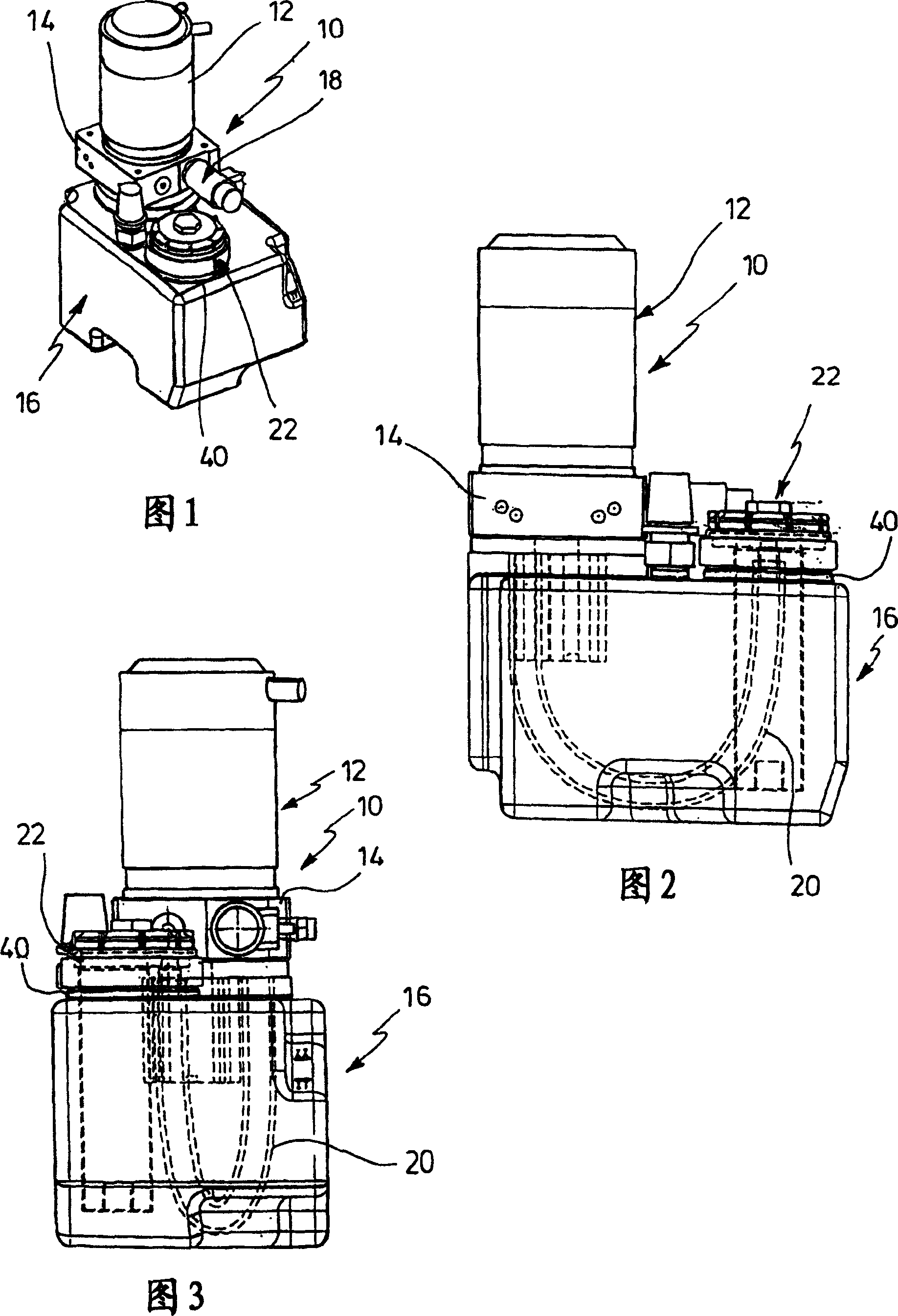
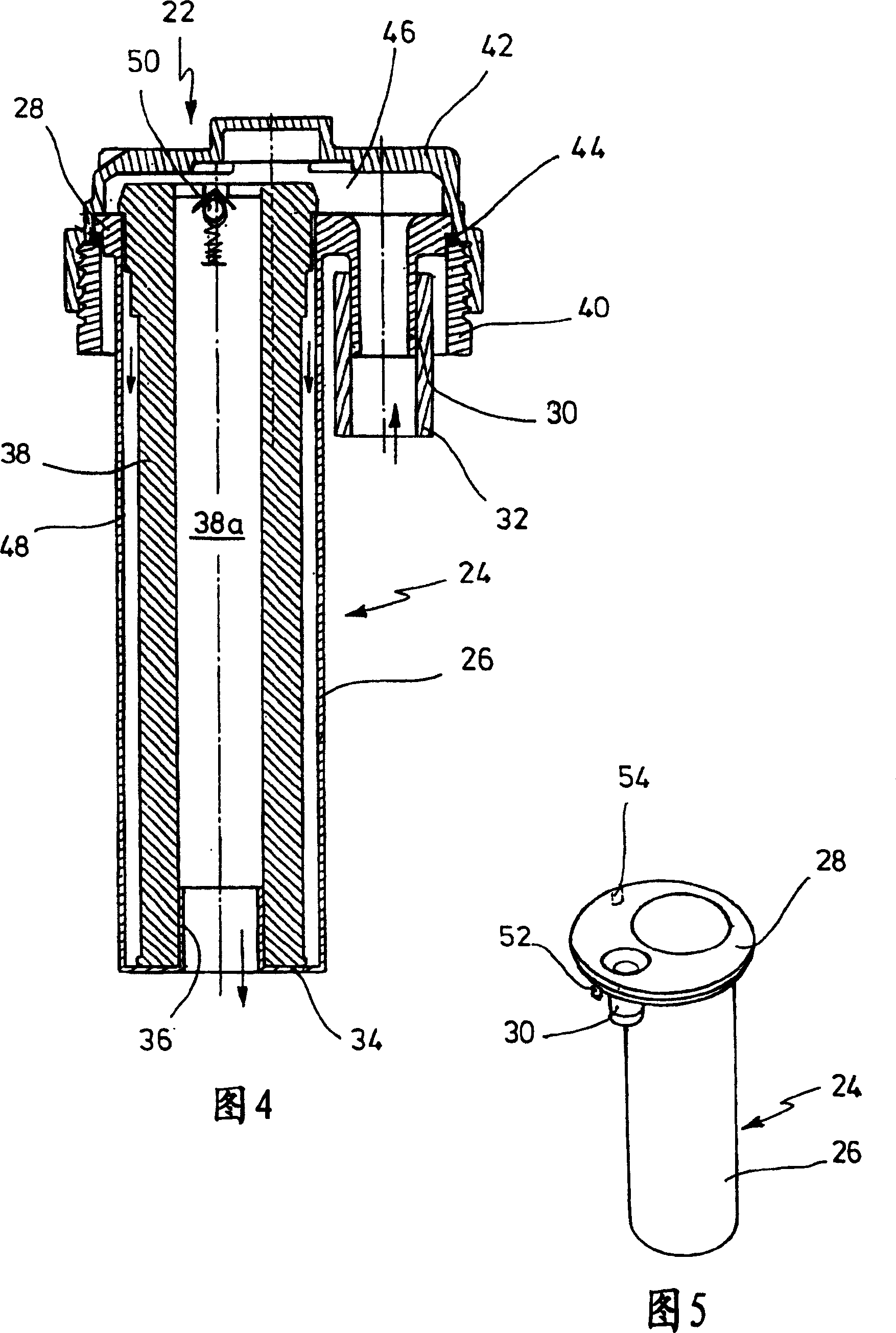
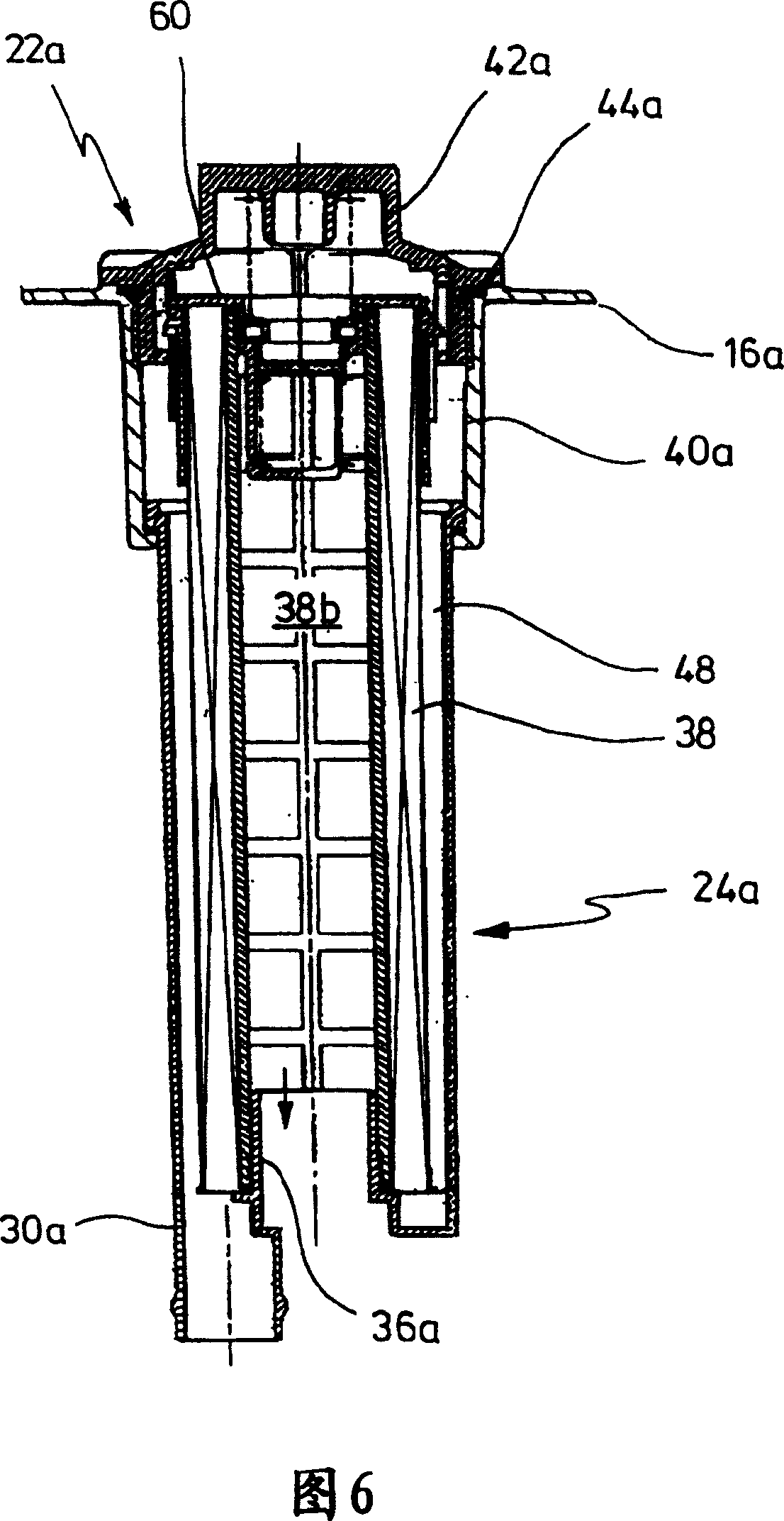
[0016] In Figures 1 to 3 a compact hydraulic unit 10 is shown with an electric motor pump unit 12 having a common housing. A valve housing 14 is secured to the casing of the motor pump unit 12, by means of which the motor pump unit 12 is mounted on the upper side of a hydraulic tank 16. A solenoid valve 18 is attached to the valve box 14 . For example, the hydraulic unit described is used to actuate a lift cylinder (not shown) in an industrial truck. When the motor of the motor pump device 12 is turned on, the liquid medium is delivered to the lifting cylinder from the storage tank 16. The valve element provides a check valve which prevents backflow of liquid media and maintains the lift cylinder at the set position. Activating the solenoid valve 18, the liquid medium will flow back from the lift cylinder, ie through a hose 20, which is shown in dashed lines in FIGS. 2 and 3 . Hoses are located within the tank 16 and lead to a filter unit 22 which will be described in more ...


PUM


Abstract

The present invention provides a hydraulic unit for industrial trucks, comprising a motor pump unit which is directly attached to a tank, a reflux filter which has an elongate filter casing for a filtering element adapted to be introduced into the tank through an opening, a hose coupling, and an outlet opening, wherein the filtering element is disposed in the flow path between the hose coupling and the outlet opening, a reflux hose between the motor pump unit and the hose coupling, and a closure for the reflux filter, wherein the reflux hose extends within the tank and the hose coupling is disposed within the tank.

Description

technical field [0001] The invention relates to a hydraulic unit for industrial trucks. Background technique [0002] Industrial trucks have a hydraulic unit that uses a load-carrying device to lift cargo. The device consists of a drive motor, most often an electric motor, a pump driven by the electric motor, and a valve. In the simplest case, a slow-acting lift cylinder is actuated by a non-return valve for holding the cargo, while releasing a circuit from the valve to the tank, for example via an openable non-return valve, to lower the cargo. [0003] It is known to combine motors, pumps and valves into units in a common housing and to place the housing directly on a liquid tank from which the pump draws the liquid medium. In addition, it is known not to send the return medium directly to the tank, but to pass it through a return filter during the cargo lowering operation. [0004] Additionally, return filters are known to be constructed such that an elongated filter ca...

Claims


Application Information

Patent Timeline
Patent Type & Authority Patents(China)
IPC IPC(8): F15B11/00F15B1/033B66F9/22F04B23/02F15B1/26F15B21/041
CPCF04B23/028B66F9/22F15B1/26B01D35/0276F15B21/041Y10T137/8085Y10T137/794Y10T137/8013
Inventor M·贝克尔
Owner JUNGHEINRICH AG
Why Eureka
Try Eureka