Antiback component of exhaust duct

An air exhaust duct and anti-backflow technology, which is applied in vertical pipes, building components, buildings, etc., can solve the problems of unsatisfactory air flow velocity at the outlet, affecting the negative pressure effect of the air duct, and deficiencies.

An air exhaust duct and anti-backflow technology, which is applied in vertical pipes, building components, buildings, etc., can solve the problems of unsatisfactory air flow velocity at the outlet, affecting the negative pressure effect of the air duct, and deficiencies.

CN100346046CInactive Publication Date: 2007-10-31吴汉木

Image

  • Antiback component of exhaust duct
  • Antiback component of exhaust duct
  • Antiback component of exhaust duct

Examples


Embodiment Construction

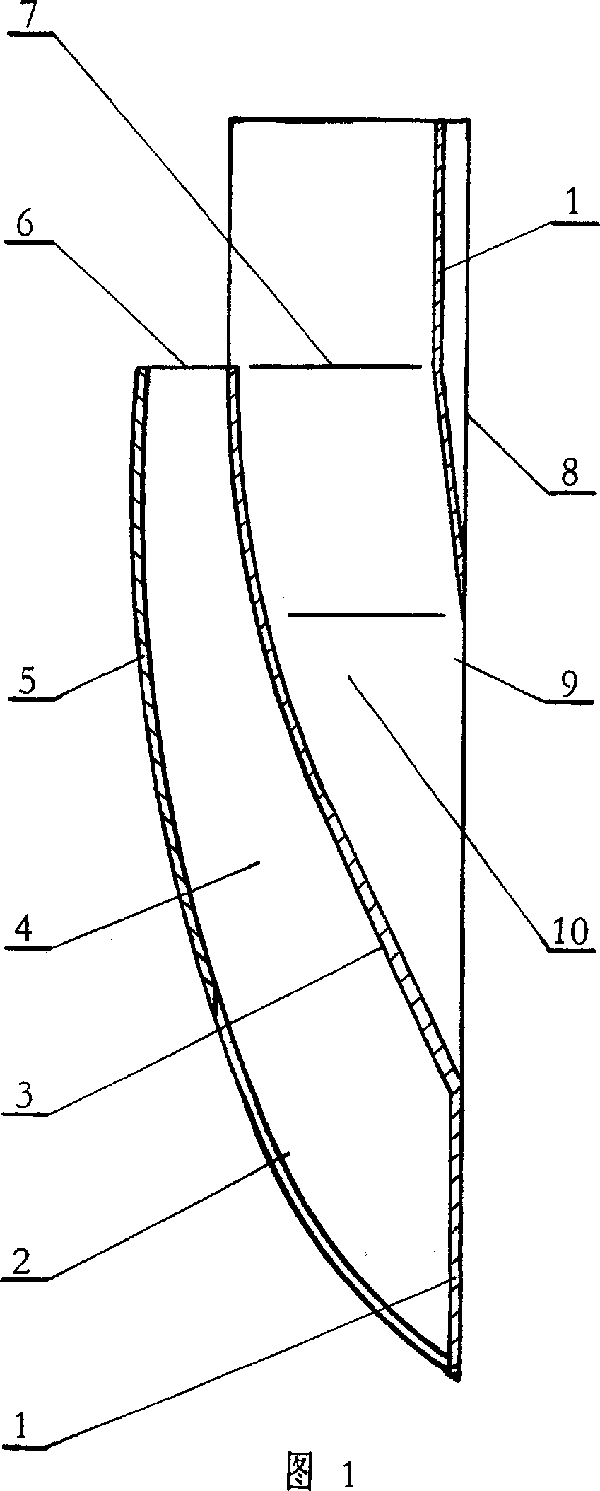
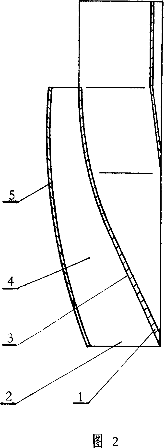
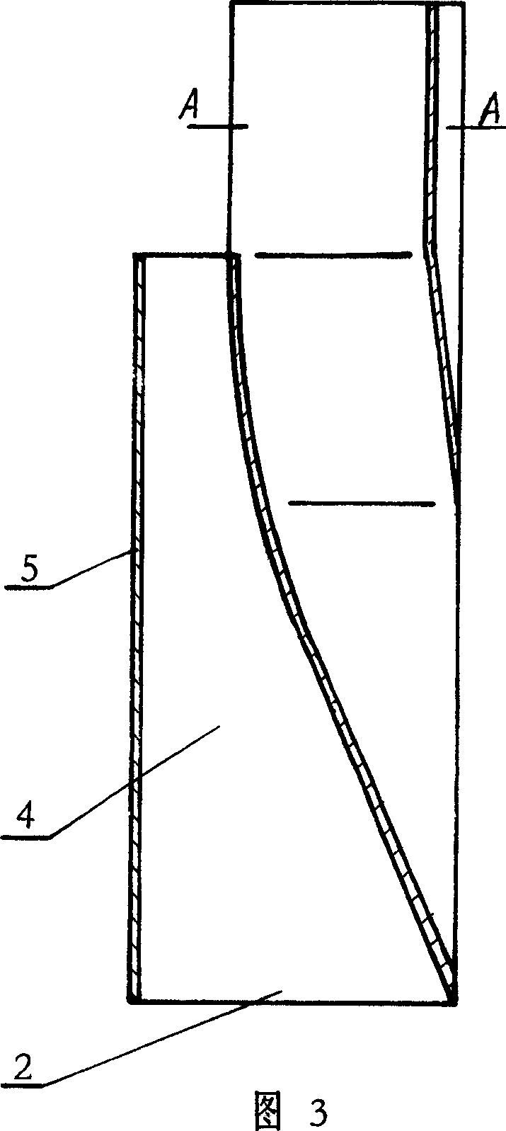
[0017] As shown in Figures 1, 2, 3, 4, 5, and 6, the present invention includes a housing 1 and a speed change plate 5 arranged on the outside of the housing. The outer shape of the housing 1 is a cone with a thin bottom and a thick top. The body 1 includes an air inlet side 8 and a shift side 3, and an air induction channel 10 is arranged in the casing 1. The shift plate 5 is a thin plate and is arranged on the outside of the shift side 3 of the casing 1. The shift plate 5 and the shift side 3 Constitute an air inlet 2 big between, the speed change hole 4 that air outlet 6 is little, housing 1 and speed change plate 5 are packed in the exhaust duct, and the outside of speed change plate 5 is the air passage in the exhaust duct. The air inlet 9 of the air induction passage 10 is arranged on the air inlet side 8, and the section from the air inlet 9 to the upward air outlet 7 gradually decreases until the air outlet 7 has the smallest section, and the section above the air outle...


PUM


Abstract

The present invention relates to anti-back component of exhaust duct which is used in the exhaust duct of the kitchen or toilet to avoid the reverse irrigate of the oil fume waste gas. The anti-back component includes shell and variable speed plate setting outside the shell, inner the shell there is guiding wind duct which shape is similar to the pot mouth with a bell mouth, there is a variable speed hole which has a big wind inlet and a small wind outlet between the variable speed lateral of the shell and the variable speed plate, the shell and variable speed plate is installed inner the exhaust duct, it is gas stream channel outside the variable speed plate. This anti-back component has simple structure, manufacture and installation is convenient, the effect of exhaust smoke is good, and can insure no reverse irrigation.

Description

Technical field: [0001] The invention relates to an anti-backflow component of the air exhaust duct used in the air exhaust duct of the kitchen and toilet to avoid the oil fume and waste gas in the exhaust duct from flowing backward. Background technique: [0002] Chinese Patent Publication No. CN1514089A discloses a kind of application number is 03126254 exhaust duct dual speed change parts, adopts this technology to realize the various working conditions of kitchen exhaust duct range hoods in small high-rise residential buildings, any use of range hoods without opening The air inlets of the exhaust ducts are all under negative pressure, which has achieved a positive effect that the oil fume and exhaust gas in the exhaust ducts will not flow back into the kitchen where the range hood is disabled. However, when it is used in the exhaust duct of high-rise residential buildings, there are still the following deficiencies: ① "The shifting side of the double speed change part an...

Claims


Application Information

Patent Timeline
31 Oct 2007
Publication
CN100346046C
IPC
E04F17/02; E04F17/04
Inventors
薛生利; 牛本银