

Optical waveguide optical spanner system
A technology of optical waveguide and optical clamp, applied in the coupling of optical waveguide, etc., can solve the problems of lack of flexibility, high price, complex structure, etc., and achieve the effect of stable capture force distribution and high degree of design freedom
- Summary
- Abstract
- Description
- Claims
- Application Information
AI Technical Summary
Problems solved by technology
Method used
Image

Examples
Embodiment 1
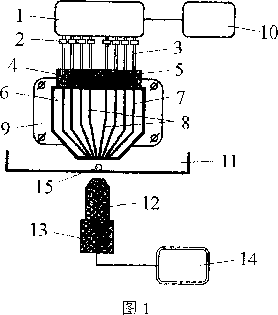
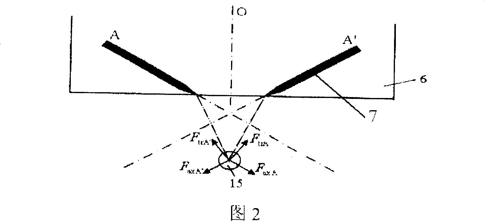
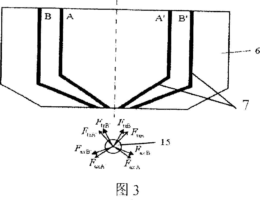
[0030] FIG. 3 is a schematic diagram of capturing particles with a planar optical waveguide optical tweezers. The optical waveguide clamp 6 has two optical waveguide groups with a common axis of symmetry: AA' and BB'. A and A' exert an axial force F on the particles 15, respectively axA , F axA′ and radial force F trA , F trA′ , B and B′ exert an axial force F on the particle 15, respectively axB , F axB′ and radial force FtrB , F trB′ , the components of the above-mentioned 8 forces in the horizontal direction are balanced, and the component forces in the vertical direction are in equilibrium with the gravity and buoyancy of the particles 15 . At this equilibrium point, the particles 15 are captured. In practical applications, the number of optical waveguide groups can be very large. By controlling the light passing conditions of the optical waveguide groups and modulating the intensity of the light source, an optical waveguide clamp can be adapted to capture different ...
Embodiment 2
[0032] There are two ways to move the particles with the planar light guide tweezers. The most direct way is to move the particles 15 trapped in the optical trap by moving the optical waveguide tweezers 6 by mechanical means. Another way is to fix the optical waveguide clamp 6 and move the particles 15 by controlling the light-passing condition of the optical waveguide group. FIG. 4 is a schematic diagram of moving the particles 15 in this way.
[0033] As shown in FIG. 4 , there are three optical waveguide groups with the same structure on the optical waveguide clamp 6: A1A1', A2A2' and A3A3', and the symmetry axes are O1, O2 and O3 respectively. At the initial position I, the particles 15 are captured by the light-passing optical waveguide group A1A1', and at this time, the light of A2A2' and A3A3' is cut off. A2A2' is then illuminated, and particle 15 is co-captured by A1A1' and A2A2', moving to position II. Then, the light of A1A1' is turned off, and the particle 15 move...
Embodiment 3
[0036] FIG. 5 is a schematic diagram of the rotating particle of the planar optical waveguide optical tweezers. The optical waveguide clamp 6 has two optical waveguide groups with the same structure: A1A1' and A2A2'. A1 and A1' are symmetrical about the axis O1, and the optical trap is located on O1 when the light is passed alone; A2 and A2' are symmetrical about the axis O2, and the optical trap is located on O2 when the light is passed alone. When the two optical waveguide groups pass light at the same time, the two optical traps jointly capture the particles 15, and the capture equilibrium point is located on the axis O. A1A1' exerts an axial force F on the particles 15 respectively axA1 , F axA1′ and radial force F trA1 , F trA1′ , A2A2' exerts axial force F on particle 15 respectively axA2 , F axA2′ and radial force F trA2 , F trA2′ . The components of the above eight forces in the horizontal direction are balanced, and the component forces in the vertical direct...
PUM
 Abstract
Description
Claims
Application Information