
Release mechanism for trigger gearshift

A technology for releasing mechanisms and sliding parts, which can be applied to bicycle gear transmission mechanisms, mechanical equipment, bicycle control systems, etc., and can solve problems such as uncontrollable slipping of rope reels

Inactive Publication Date: 2007-11-14
SRAM
View PDF7 Cites 1 Cited by
  • Summary
  • Abstract
  • Description
  • Claims
  • Application Information

AI Technical Summary

Problems solved by technology

While the actual position of the cable reel is fixed by means of a spring-loaded detent, the detent remains effective only up to a certain fixing force and can then allow the pretensioned cable reel to be disabled by the shift cable. skidding

Method used


Image

  • Release mechanism for trigger gearshift
  • Release mechanism for trigger gearshift
  • Release mechanism for trigger gearshift

Examples


Embodiment Construction

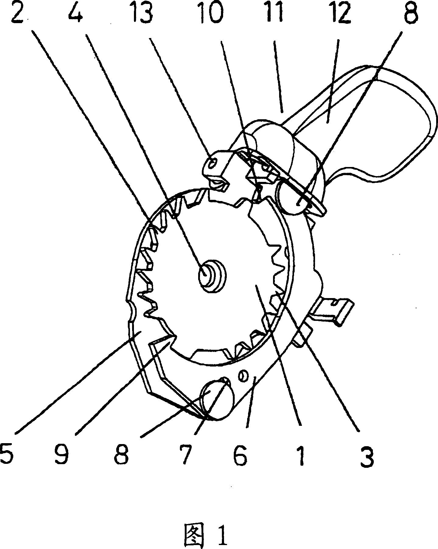
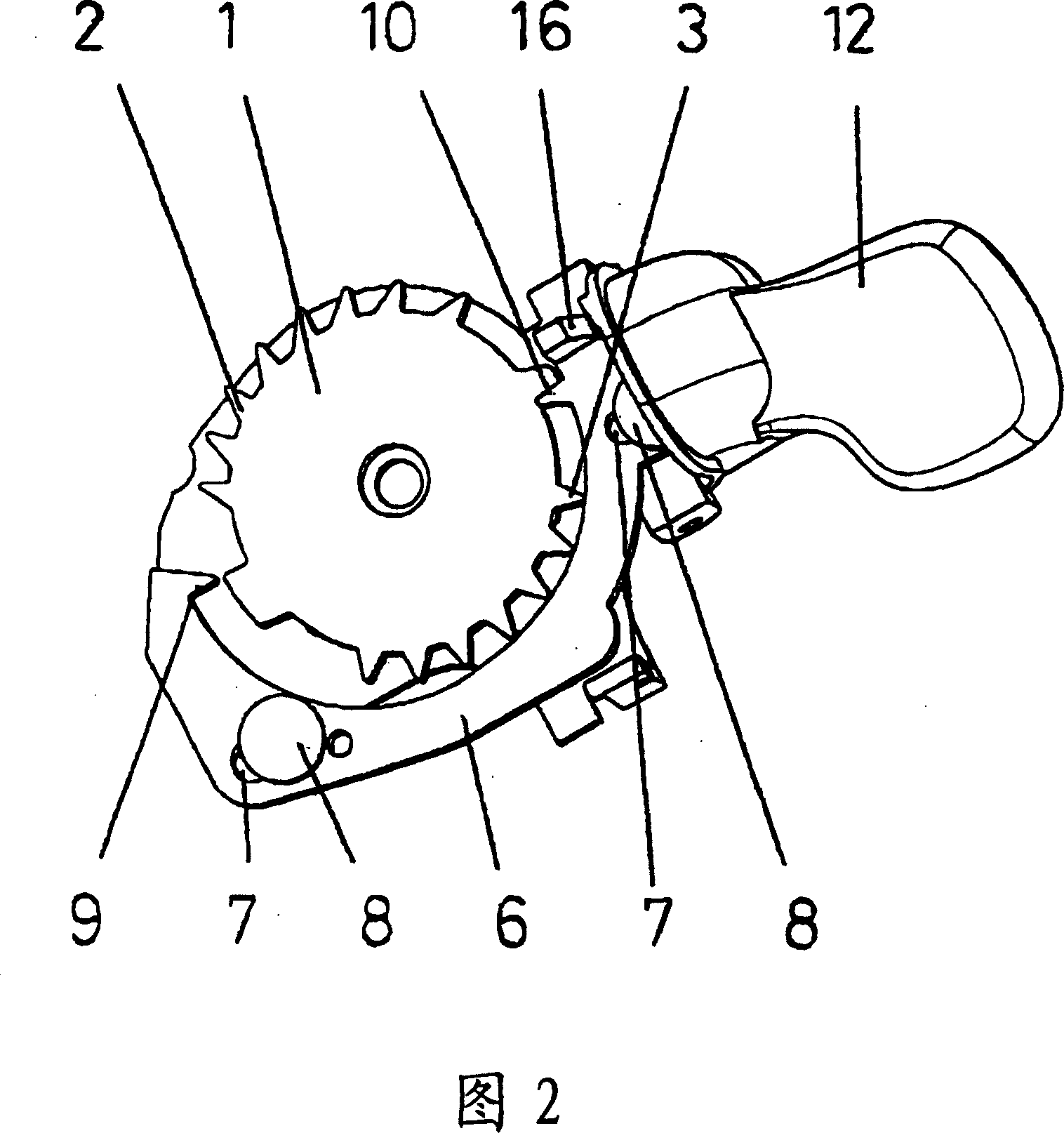
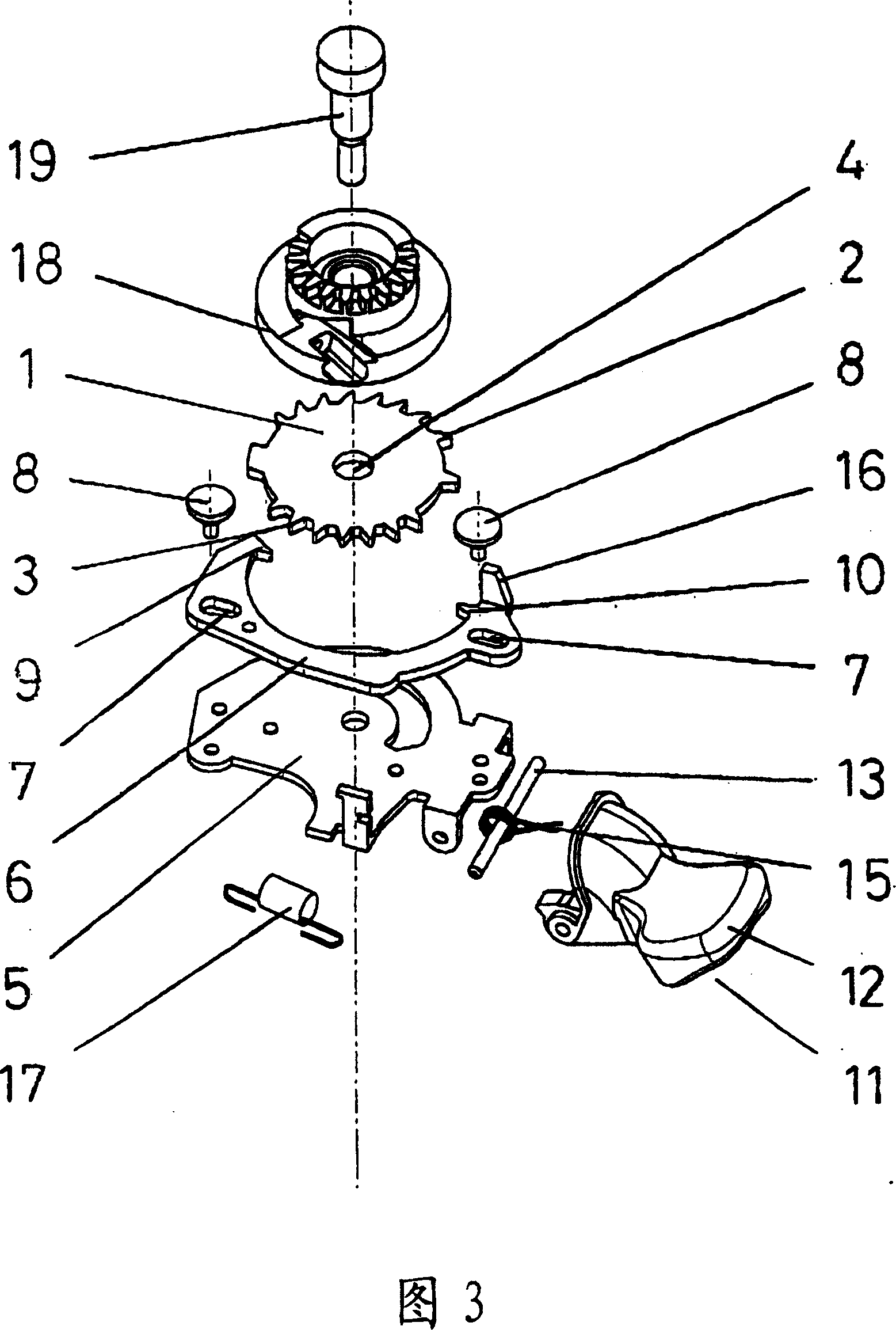
[0022] Fig. 1 has shown the structural arrangement on the basic position of the member (without rope reel) that basically participates in the release process. The gear plate 1 carries the stop tooth 2 and the catch tooth 3 on the circumference. The stop tooth 2 and the catch tooth 3 are arranged at opposite corresponding positions and have different tooth profile structures. The retaining tooth 2 has a pronounced saw-tooth profile with a steep tooth flank and a gently sloping tooth flank. In the center of the gear wheel there is a bore 4 for accommodating a central shaft which is guided in a housing part 5 . The sliding part 6 has two elongated hole guide structures 7 and is movably hinged on the housing part 5 by means of two guide pins 8 . The sliding member 6 surrounds and holds the chainring 1 and is provided with two rigid jaws. In the base position shown, the locking pawl 9 engages in a tooth groove of the locking tooth 2 . At this time, the catching pawl 10 is in a ...


PUM


Abstract

A release mechanism, for releasing a draw mechanism for controlling a bicycle driving device, includes a cable spool (18) for winding the pre-tensioned shift drawing pieces, a release device for fixing or release the cable spool (18) tensioned by the shift drawing pieces in the loosening direction, an operation elememt (11) for guiding the release process, as well as a housing piece (5) for holding and guiding the pieces. The release device essentially includes: a toothed disk (1) connected to the cable spool (18), and a slide unit (6) with opposing pawls (9,10); the pawls (9,10) are alternatively engaged at the circumference of the toothed disk (1) in the release process. The advantage of this release-device is in the reliable positive-locking holding function and in the simple and compact realization of the moving parts and the teeth-gear. The triggering process runs in continuously controlled switch-tips and with a higher precision.

Description

technical field [0001] The invention relates to a release mechanism for releasing a shift cable of a bicycle shift device in a step-by-step manner. Background technique [0002] The utility model DE9015515 discloses a step shifter for controlling a bicycle transmission, and its lever is equipped with a pair of claws. The gripper is gripped on a gear plate that is connected to a cable reel for winding the shift cable. When the lever is actuated in the tensioning or releasing direction, the corresponding gear is engaged and thus a correspondingly configured shifting path is achieved by winding or unwinding the shift cable on the circumference of the cable reel. After the shift lever has been actuated, regardless of the direction, it always returns to its ready position. In order to position the cable reel in each of the shifted positions, a friction device or locking device is provided which is accommodated in the housing of the selector and interacts with the cable reel or ...

Claims


Application Information

Patent Timeline
Patent Type & Authority Patents(China)
IPC IPC(8): B62M25/04B62K23/06
CPCB62M25/04B62K23/06Y10T74/214Y10T74/2141Y10T74/20402
Inventor R·维泽尔
Owner SRAM
Learn More