
Air conditioner and method of controlling air conditioner

An air conditioner and control part technology, which is applied in the field of air conditioner and air conditioner control, and can solve problems such as discomfort

Inactive Publication Date: 2007-12-19
DAIKIN IND LTD
View PDF8 Cites 0 Cited by
  • Summary
  • Abstract
  • Description
  • Claims
  • Application Information

AI Technical Summary

Problems solved by technology

In this way, when conventional air conditioners perform cooling operation and dehumidification operation, people in the room may feel uncomfortable.

Method used


Image

  • Air conditioner and method of controlling air conditioner
  • Air conditioner and method of controlling air conditioner
  • Air conditioner and method of controlling air conditioner

Examples


Embodiment Construction

[0027]

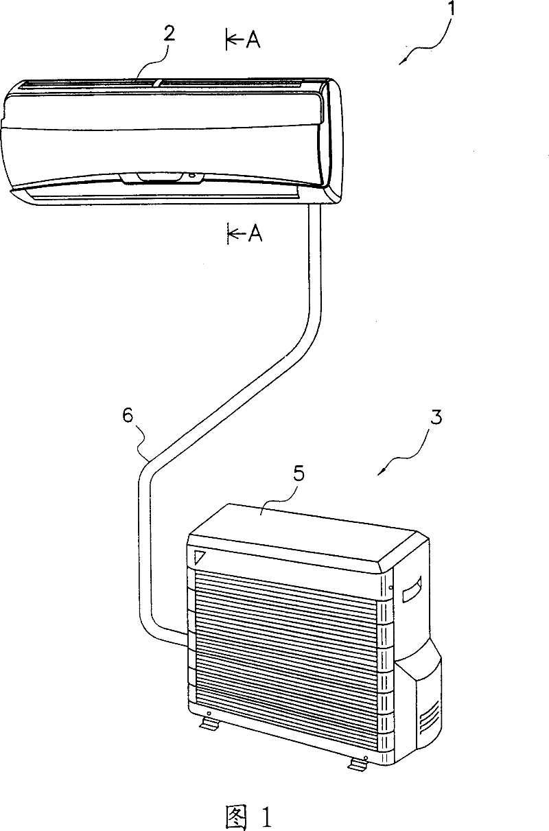
[0028] Fig. 1 shows an external view of an air conditioner 1 according to an embodiment of the present invention.

[0029] The air conditioner 1 is a device that sends conditioned air that has been processed such as cooling or heating and dehumidification to the room to condition the indoor air. Such an air conditioner 1 includes an indoor unit 2 installed on an upper portion of an indoor wall, and an outdoor unit 3 installed outdoors. The outdoor unit 3 has an outdoor air-conditioning unit 5 in which an outdoor heat exchanger, an outdoor fan, and the like are installed.

[0030] An indoor heat exchanger is installed inside the indoor unit 2, and an outdoor heat exchanger is installed inside the outdoor air-conditioning unit 5. Each heat exchanger and refrigerant pipes 6 connecting these heat exchangers constitute a refrigerant circuit.

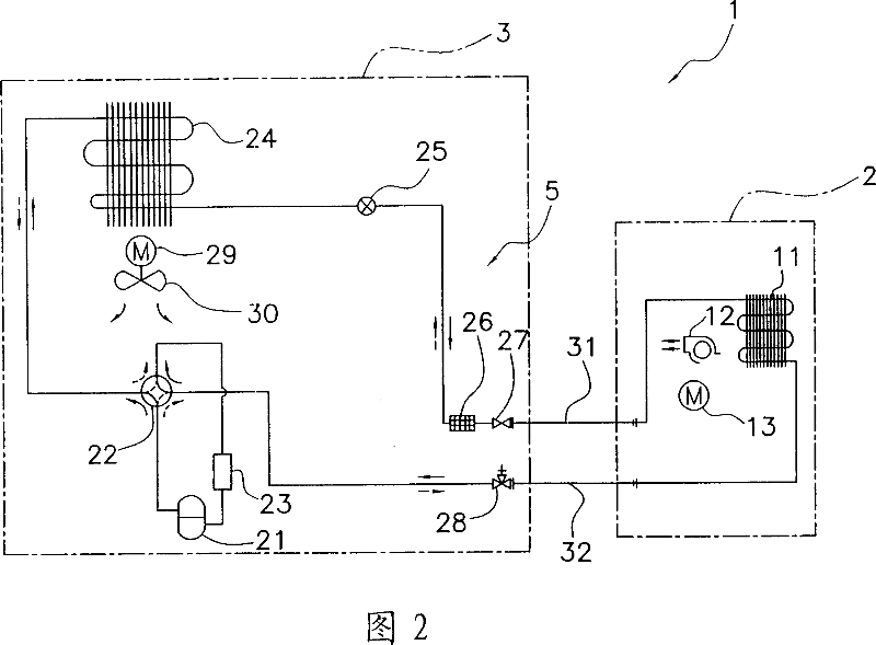
[0031] FIG. 2 shows a system diagram of a refrigerant circuit for the air conditioner 1 .

[0032] An indoor heat exchanger 11 ...


PUM


Abstract

An air conditioner capable of reducing a possibility that comfortableness for an inhabitant in a room is lost and allowing at least one of a cooling operation and a dehumidifying operation, comprising air blowing parts (12, 13), a flap (144), and a control part (60), wherein the air blowing parts (12, 13) blow conditioned air into the room, the flap (144) determines the discharge direction of the air blown from the air blowing parts (12, 13), and the control part (60) performs a first control to change the swing speed of the flap (144) according to a room temperature.

Description

technical field [0001] The present invention relates to an air conditioner and a control method for the air conditioner, and more particularly, to an air conditioner capable of performing at least one of a cooling operation and a dehumidification operation, and a control method for the air conditioner. Background technique [0002] Conventionally, air conditioners installed in houses, buildings, etc. to improve indoor comfort by sending conditioned air into the room are known. This type of air conditioner keeps the indoor temperature at a comfortable temperature for occupants by sending cold or hot air into the room, so as to improve indoor comfort. [0003] This type of air conditioner has a wind direction plate for determining an exhaust direction of fed conditioned air. In order to make the conditioned air reach all corners of the room, most of these wind direction boards swing at a certain speed. [0004] However, in this air conditioner, since the swing speed of the w...

Claims


Application Information

Patent Timeline
Patent Type & Authority Patents(China)
IPC IPC(8): F24F11/02F24F11/00
CPCF24F2001/0048F24F11/0078F24F1/0011F24F11/0012F24F11/30F24F2110/10F24F11/79F24F1/0057F24F11/84F24F11/64F24F11/86F24F11/56F24F11/74F24F13/08
Inventor 河野重富西浦良广松原笃志
Owner DAIKIN IND LTD
Features
  • Generate Ideas
  • Intellectual Property
  • Life Sciences
  • Materials
  • Tech Scout
  • Unparalleled Data Quality
  • Higher Quality Content
  • 60% Fewer Hallucinations
Learn More