Supercharge Your Innovation With Domain-Expert AI Agents!

Reciprocally swinging transmission

A technology of reciprocating swing and transmission, applied in transmission, friction transmission, belt/chain/gear, etc., to achieve the effect of increasing rotational speed

Inactive Publication Date: 2008-01-09
欧子文 +1
View PDF3 Cites 0 Cited by
  • Summary
  • Abstract
  • Description
  • Claims
  • Application Information

AI Technical Summary

Problems solved by technology

Obviously, in the existing mechanical transmission mechanism, there is no mechanism that is a reciprocating swing transmission mechanism.

Method used


Image

  • Reciprocally swinging transmission
  • Reciprocally swinging transmission
  • Reciprocally swinging transmission

Examples


Embodiment 1

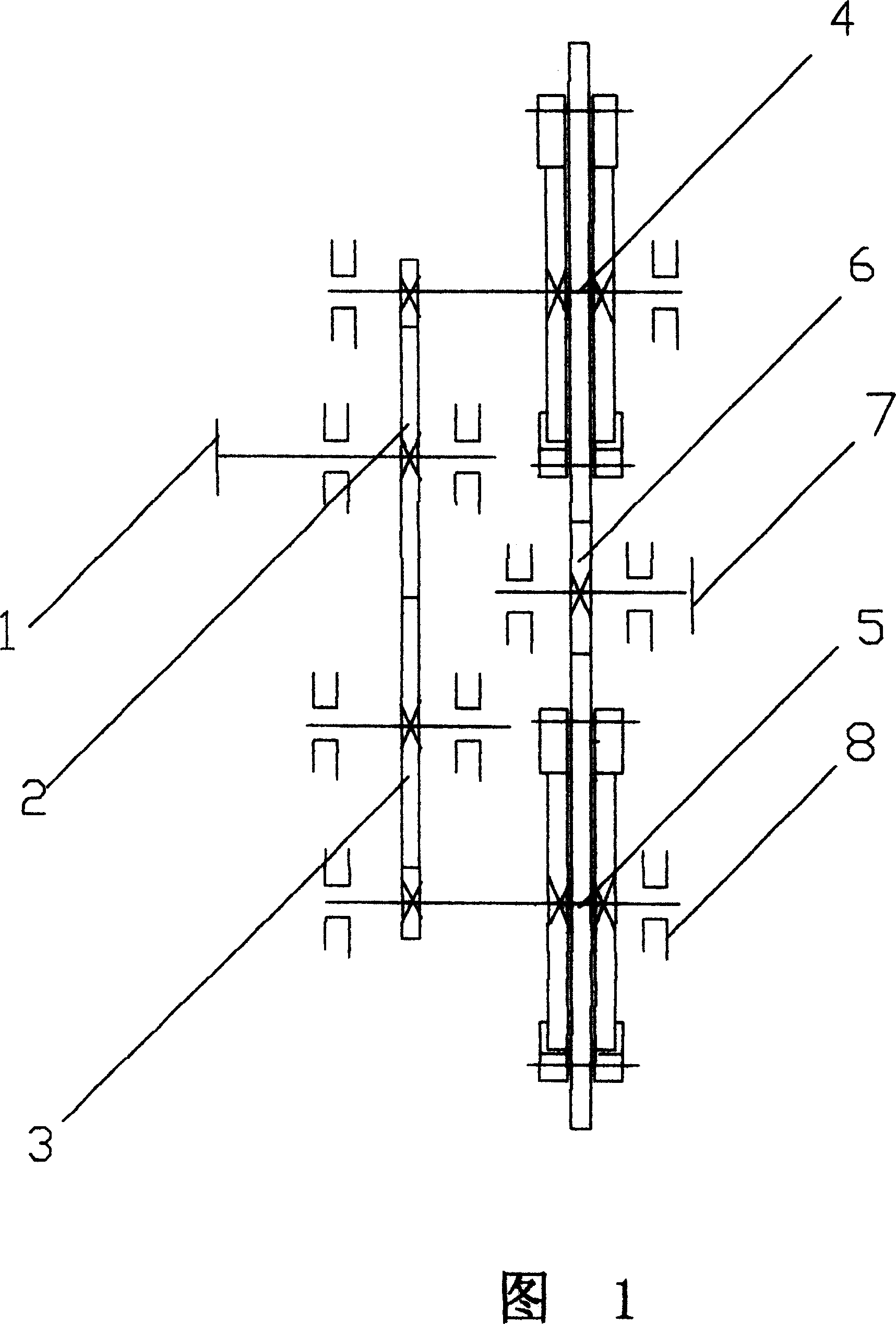
[0027] Embodiment 1, the reciprocating oscillating transmission device of single reciprocating oscillating shaft (as shown in Figure 1)

[0028] The reciprocating oscillating transmission device with a single reciprocating oscillating shaft is suitable for use on devices such as single-blade oscillating wind power devices, and its internal structure is shown in Figure 1.

[0029] When the reciprocating oscillating transmission device with a single reciprocating oscillating shaft is used in a single-blade oscillating wind power device, the horizontal shaft of the wind power device is connected with the reciprocating oscillating shaft, and the output shaft is connected with the coupling of the generator, so that it can work normally. When the blades swing left and right, the reciprocating swing transmission device converts the swinging mechanical energy of the blades into mechanical energy of continuous rotation in the same direction for the generator to generate electricity.

Embodiment 2

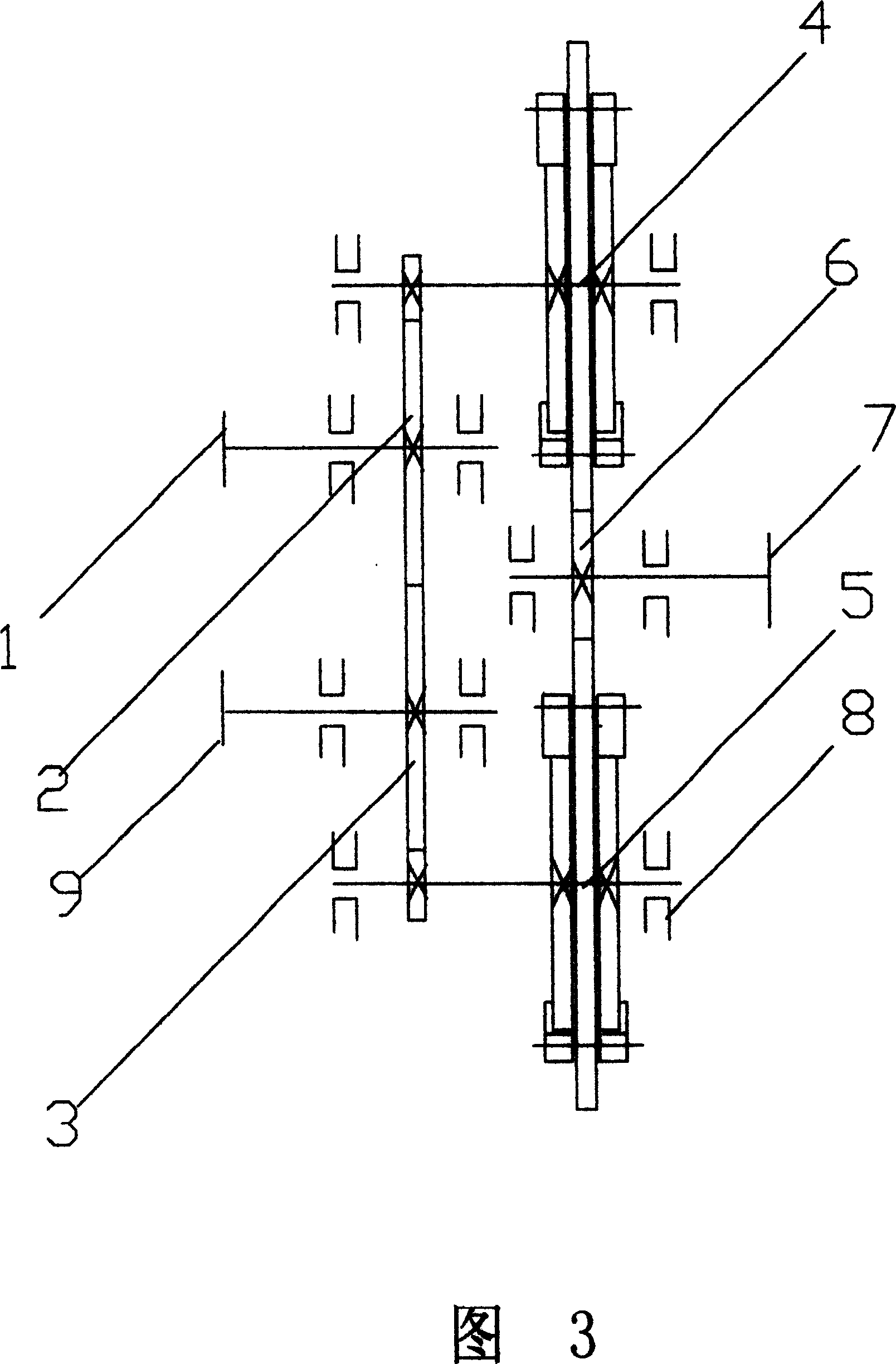
[0030] Embodiment 2, a reciprocating swing transmission device with double reciprocating swing shafts on one side (as shown in Figure 3)

[0031] The reciprocating swing transmission device with double reciprocating swing shafts on one side is based on the reciprocating swing transmission device, the shaft of the reciprocating transmission gear 3 is lengthened, and then a shaft coupling is assembled to form the second reciprocating swing shaft 9 . In the reciprocating oscillating transmission device with double reciprocating oscillating shafts on one side, the reciprocating transmission gear 3 and the reciprocating oscillating gear 2 are also reciprocating oscillating gears. These two gears are both reciprocating oscillating gears, transmission gears, and synchronous gears. The reciprocating oscillating transmission device with double reciprocating oscillating shafts on one side is especially suitable for use on unilateral double blades oscillating wind power devices. During in...


PUM


Abstract

The present invention relates to mechanical engineering and is especially one reciprocally swinging transmission device. The reciprocally swinging transmission device is used to convert the reciprocal swinging into continuous rotation in the same direction, and is especially suitable for use in a swinging wind driven apparatus. It has a gear transmission system A and a gear transmission system B to convert the mechanical energy the right and left swinging blade generates into the output one-way continuous rotating mechanical energy alternately for the generator to produce electricity. The basic structure of the reciprocally swinging transmission device is given.

Description

Technical field [0001] The invention relates to mechanical engineering, in particular to a transmission device. Background technique [0002] In the prior art, there are many types of transmission devices, but in terms of the performance of the input and output motion state transformation, there are mainly the following six types: rotation to rotation, movement to rotation, rotation to movement, movement to movement, transfer (shift) ) dynamic compound movement, compound movement change (moving) movement. [0003] In the prior art, there are only ratchet mechanisms and overrunning ratchet mechanisms that can convert swinging motions into rotational motions. However, whether it is a ratchet mechanism, an overrunning ratchet mechanism driven by a pawl, or an overrunning ratchet mechanism driven by friction, it can only convert the swinging motion in one direction into a rotating motion, while the swinging motion in the opposite direction cannot Can not in this mechanism, it ...

Claims


Application Information

Patent Timeline
IPC IPC(8): F16H19/08
Inventor 欧子文欧亚
Owner 欧子文
Features
  • R&D
  • Intellectual Property
  • Life Sciences
  • Materials
  • Tech Scout
  • Unparalleled Data Quality
  • Higher Quality Content
  • 60% Fewer Hallucinations
Learn More