Oil-sand separator and method for removing sand and sealing

A technology of separator and oil sand, which is applied in the direction of earthwork drilling, production fluid, wellbore/well parts, etc., which can solve the problems of labor-intensive, low work efficiency, long processing time, etc., and achieve environmental pollution and work efficiency High, good sand removal effect

Inactive Publication Date: 2008-01-16
NORTH CHINA UNIVERSITY OF SCIENCE AND TECHNOLOGY
View PDF3 Cites 0 Cited by
  • Summary
  • Abstract
  • Description
  • Claims
  • Application Information

AI Technical Summary

Problems solved by technology

Its shortcomings are: long processing time, labor-intensive, low work efficiency, and it takes a lot of cultivated land, polluting the environment

Method used


Image

  • Oil-sand separator and method for removing sand and sealing
  • Oil-sand separator and method for removing sand and sealing

Examples


Embodiment Construction

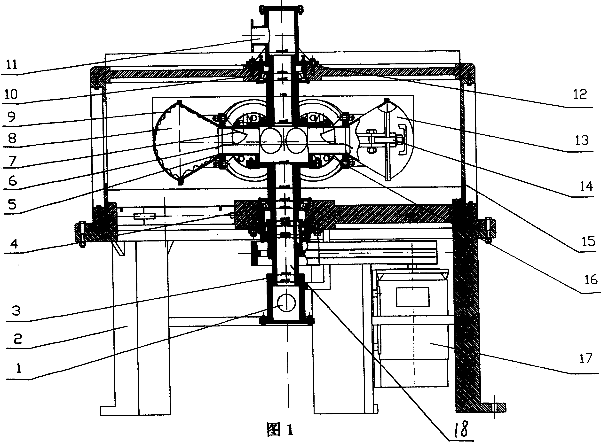
[0011] The present invention will be further described below in conjunction with the accompanying drawings and embodiments.

[0012] Separator of the present invention is made up of base 2, upper and lower bearing 10,4, drum 16, drum shaft 18 etc. Referring to accompanying drawing 1 , the bracket 15 is fixedly installed on the base 2 .

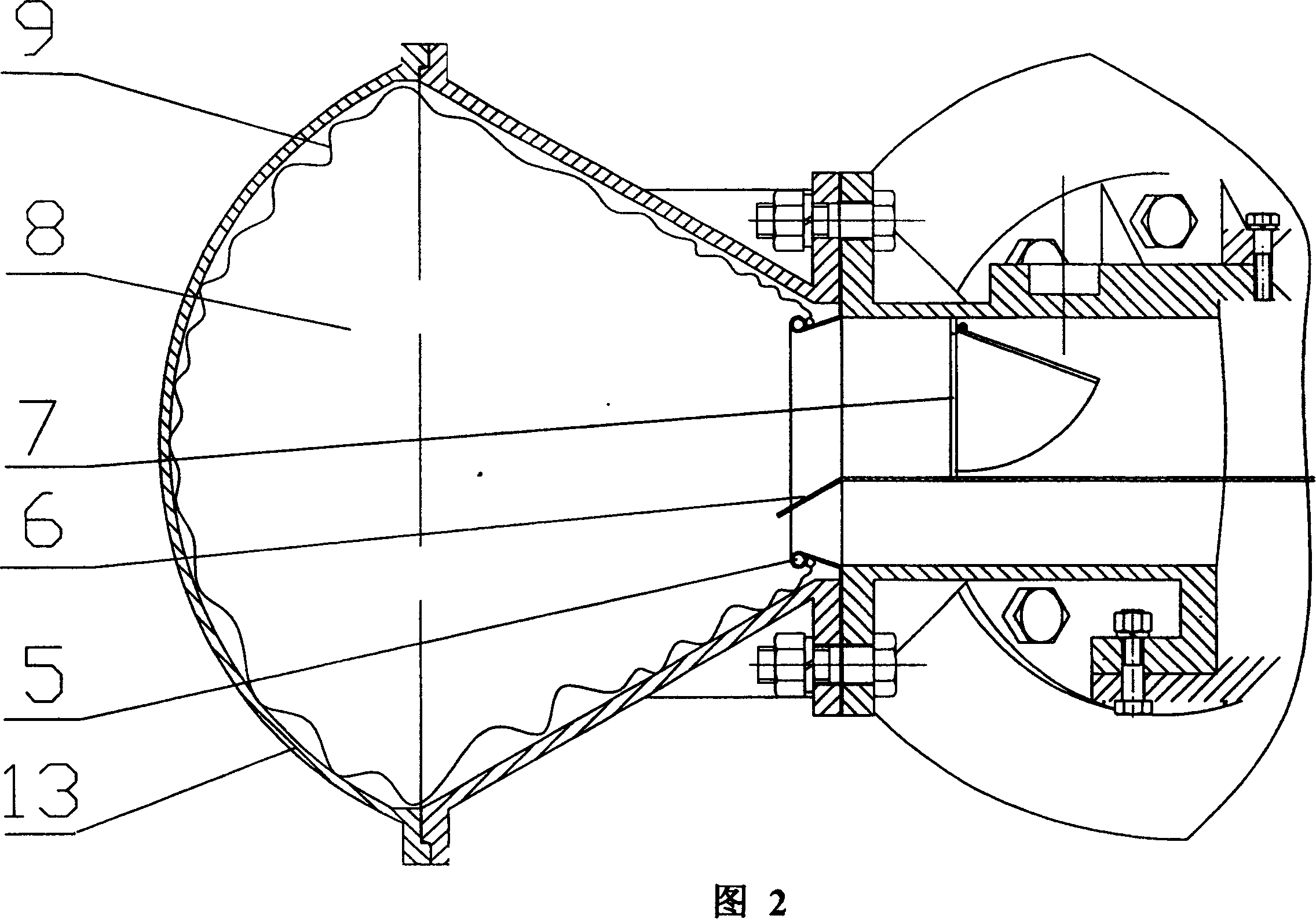
[0013] The drum shaft 18 is a hollow shaft, supported and installed in the center of the bracket 15 by the upper bearing 10 and the lower bearing 4, and its upper end is connected with the upper joint. It is connected with the lower joint, and the contact between the lower joint and the drum shaft 18 is provided with a sealing ring 3 . An oil outlet 11 is arranged on the upper joint, and the oil outlet 11 communicates with the upper joint. The lower joint is provided with an oil inlet 1, and the oil inlet 1 communicates with the lower joint. The rotating drum 16 is connected with the rotating drum shaft 18 and placed horizontally at the cen...


PUM


Abstract

The present invention relates to oil and sand separating machine and sand discharge and sealing method. Said separating machine includes base seat, oil inlet, oil outlet, drive motor, supporting frame, drum tumbler and drum tumbler shaft, several sand cavities, hanging ring, sealing bag, sand-discharging gate, flow deflector and check valve, etc. Said invention also provides their connection mode and mounting method. Besides, said invention also provides its working principle.

Description

technical field [0001] The invention relates to the technical field of separation of oil sand from petroleum, in particular to an oil sand separator which can separate fine sand particles from petroleum and quickly discharge the hardened sand blocks after separation, as well as sand discharge and sealing. Methods. Background technique [0002] The exploited oil contains a lot of sand, among which the larger particles of sand can be easily separated by a centrifuge, and the separated sand can be discharged out of the centrifuge. But also contain a lot of fine grains of sand in oil, it is difficult to discharge it out of the machine with existing devices. The reason is that the oil has a high density and a high viscosity, and the fine sand particles in the oil have a small particle size and are in a suspended state in the oil, and cannot be separated by gravity. If the existing centrifuge (such as a horizontal screw centrifuge) is used ) Since the sand grains are very fine a...

Claims


Application Information

Patent Timeline
Patent Type & Authority Patents(China)
IPC IPC(8): E21B43/34
Inventor 王家金关启明路春光李占贤李建功孟宪举谢世满霍平吴涛
Owner NORTH CHINA UNIVERSITY OF SCIENCE AND TECHNOLOGY
Why Eureka
Try Eureka