Check patentability & draft patents in minutes with Patsnap Eureka AI!

Coaxial connector

A coaxial connector, barrel technology, applied in the direction of connection, two-part connection device, parts of the connection device, etc., can solve the problems of interrupted connection, damaged connector, etc.

Inactive Publication Date: 2008-01-30
HOSIDEN CORP
View PDF7 Cites 0 Cited by
  • Summary
  • Abstract
  • Description
  • Claims
  • Application Information

AI Technical Summary

Problems solved by technology

Therefore, depending on the state around the circumference of the coaxial connector 10, undesirable external force may be applied to the top 190 of the barrel insulator 19 from a specific direction, thereby interrupting the connection or destroying the connector.

Method used


Image

  • Coaxial connector
  • Coaxial connector
  • Coaxial connector

Examples


Embodiment Construction

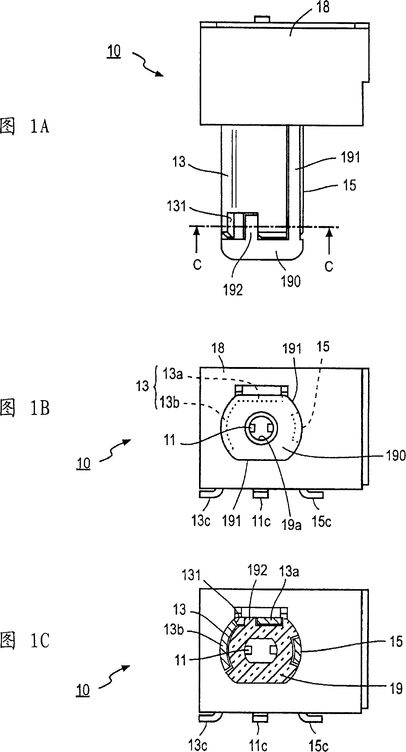
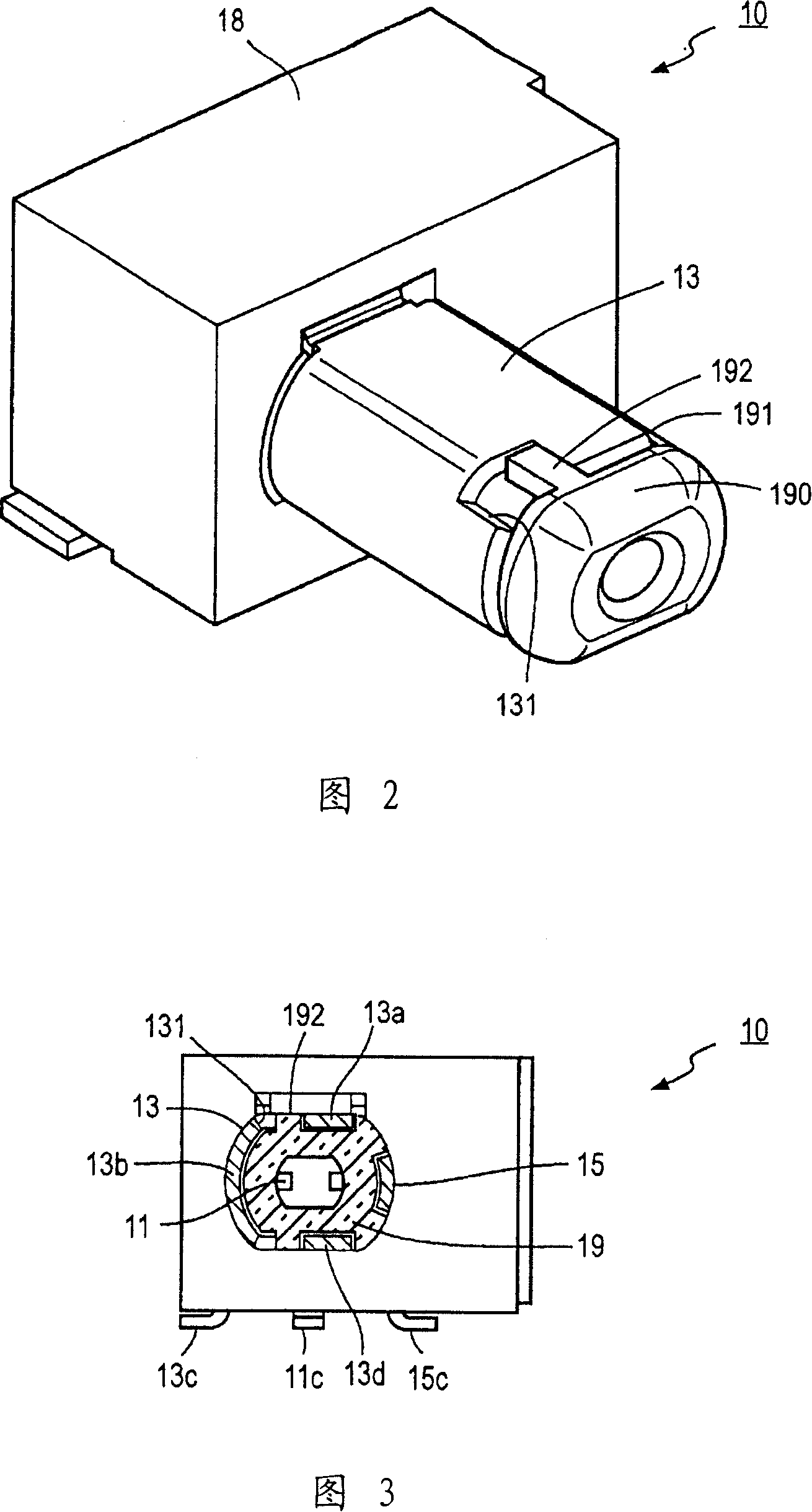
[0025] An embodiment of a coaxial connector according to the present invention will be described with reference to FIGS. 1A , 1B, 1C and 2 . FIG. 1A shows the coaxial connector seen from above, and FIG. 1B shows the coaxial connector seen from the front; FIG. 1C shows a cross-sectional view taken along line C-C of FIG. 1A . Fig. 2 is a perspective view of the coaxial connector. In this embodiment, the same reference numerals denote the same elements as those in the conventional example in FIGS. 5A and 5B.

[0026] The coaxial connector 10 described with reference to FIGS. 1A, 1B, 1C and 2 represents a coaxial connector that can be mated with and detached from a mating coaxial connector not shown.

[0027] In this embodiment, the cylindrical insulator 19 is integrally formed to protrude vertically from one surface of the substantially rectangular insulating base 18 . The top 190 of the cylindrical insulator 19 has a large diameter, and the upper and lower side surfaces facing...


PUM


Abstract

In a coaxial connector, a cylindrical insulator 19 is integrally formed to protrude from one surface of a substantially rectangular insulation base 18, and a tip portion 190 of the cylindrical insulator 19 has an enlarged diameter. An outer conductor shell 13 is provided that covers a circumferential surface of the cylindrical insulator on the side closer to the insulation base 18 than the tip portion 190. A notch 131 is formed in a front edge of the outer conductor shell 13 and a protrusion 192 formed to protrude from a rear end of the tip portion 190 of the cylindrical insulator 19 toward the insulator base 18 enters the notch 131 so that the notch 131 and the protrusion 192 engage each other in a circumferential direction of the cylindrical insulator 19.

Description

technical field [0001] The present invention relates to a coaxial connector, and more particularly to such a coaxial connector, wherein the outer conductor shell partially covers a cylindrical insulator having inner conductor contacts, and the left and right side surfaces or the upper and lower side surfaces of the cylindrical insulator One or more surfaces of the exposed. Background technique [0002] A conventional example of a coaxial connector will be described with reference to FIGS. 5A and 5B . This example is, for example, the I / O connector 100 of a mobile phone disclosed in Japanese Patent Application Laid-Open No. 2003-323949, and the coaxial connector 10 and the multi-connector jack 17 are provided on the same base 18 . Figure 5A shows the coaxial connector 10 and the multi-connector receptacle 17 seen from above, wherein the metal housing 12 of the I / O connector 100 is cut in half, while Figure 5B shows the front view from the installation direction to the I / O c...

Claims


Application Information

Patent Timeline
Patent Type & Authority Patents(China)
IPC IPC(8): H01R24/02H01R13/629H01R24/38
Inventor 政木阳一朗
Owner HOSIDEN CORP
Features
  • R&D
  • Intellectual Property
  • Life Sciences
  • Materials
  • Tech Scout
  • Unparalleled Data Quality
  • Higher Quality Content
  • 60% Fewer Hallucinations
Learn More