Thermocouple temperature monitoring method and system for air preheater

An air preheater and thermocouple technology, applied to thermometers, thermometers, and combustion methods that use directly heat-sensitive electric/magnetic elements, can solve problems such as false alarms, ignition of heating elements, and fires , to achieve the effect of improving reliability, increasing reliability and service life, and reducing judgment interference

Inactive Publication Date: 2008-02-06
SHANGHAI BOILER WORKS +1
View PDF5 Cites 0 Cited by
  • Summary
  • Abstract
  • Description
  • Claims
  • Application Information

AI Technical Summary

Problems solved by technology

[0002] The air preheater is an important supporting equipment for large generator boilers. Inside the air preheater, the incompletely burned accumulation deposited on the surface of the heating element will easily generate hot spots when encountering sufficient oxygen at the air inlet. If the hot spots are slow Slow diffusion will cause the heating element to catch fire and form a fire, which will cause serious and irreparable losses. In order to prevent the air preheater from igniting, it is necessary to install monitoring devices in the air preheater system. Commonly used are infrared hot spot detection detectors and thermocouple detectors, their detection principle only monitors the temperature at the air inlet or outlet of the air preheater, ignoring the influence of temperature fluctuations at the inlet and outlet of other parts of the air preheater on the temperature rise of the entire air preheater The impact is to use the absolute value of the comparison temperature to determine whether there is a hot spot. These devices still have some problems in terms of safety, reliability and service life, and are prone to false alarms.

Method used


Image

  • Thermocouple temperature monitoring method and system for air preheater
  • Thermocouple temperature monitoring method and system for air preheater
  • Thermocouple temperature monitoring method and system for air preheater

Examples


Embodiment Construction

[0040] The present invention will be further described below in conjunction with accompanying drawing and embodiment, take the air preheater of 300MW boiler as an example.

[0041] The devices required for the present invention include:

[0042] (1) 30 dedicated thermocouple probes;

[0043] (2) Special thermocouple probe installation tube;

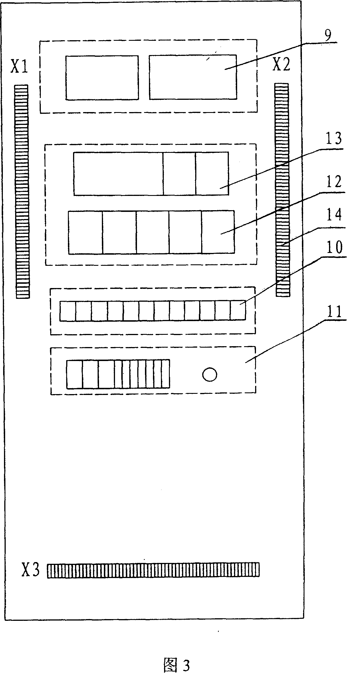
[0044] (3) Control cabinet

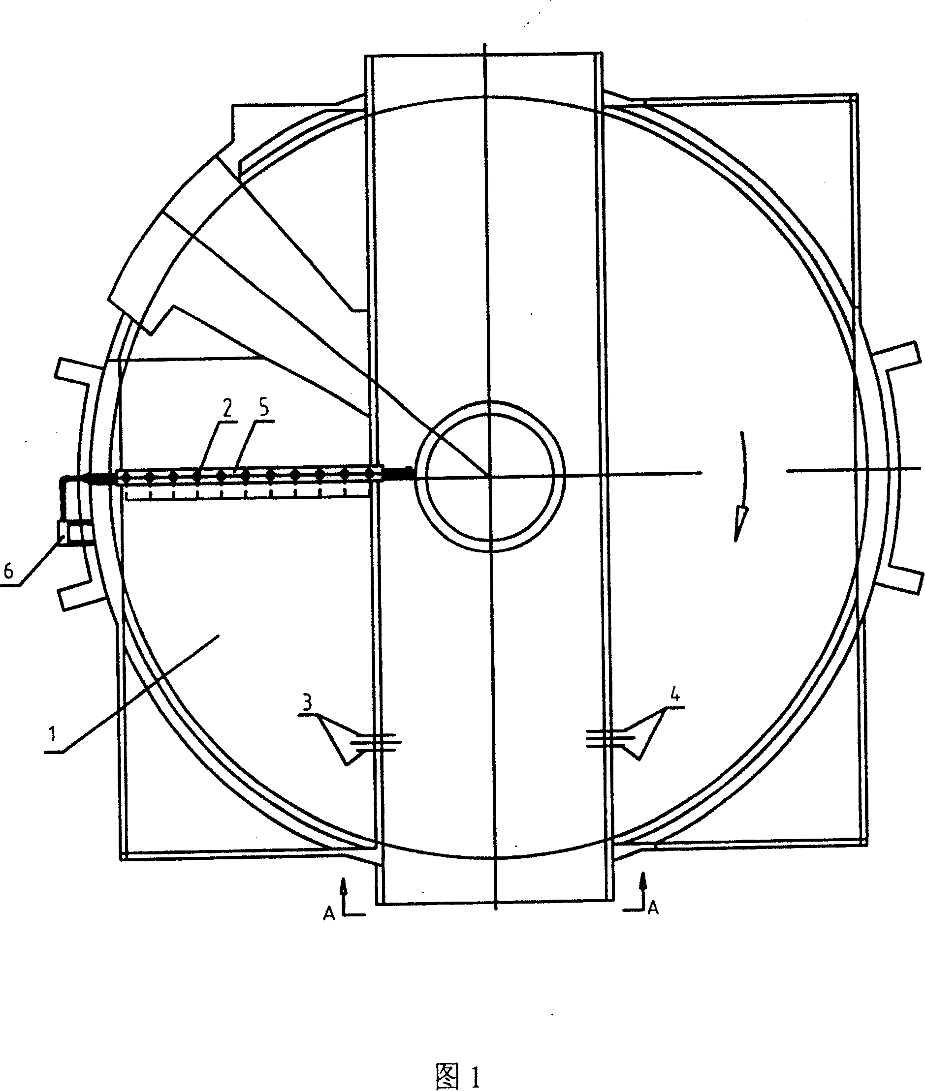
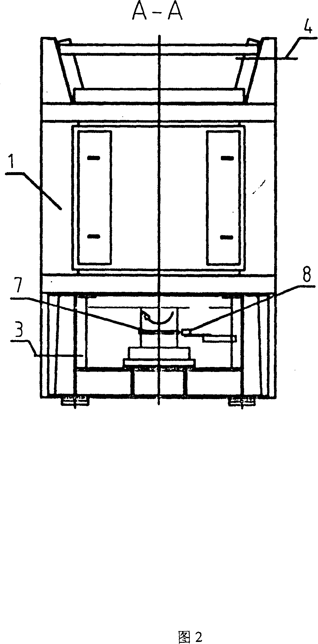
[0045] As shown in Figure 1 and 2, it is the layout diagram of the thermocouple probes of the air preheater, which consists of air preheater 1, 11 dedicated thermocouple probes at the two sets of air outlets, and 2 dedicated thermocouple probes at the two sets of air inlets. Couple probe 3, 2 special thermocouple probes at two groups of smoke inlets 4, thermocouple group installation tube 5, local junction box 6, stop alarm sensor collar 7, and proximity switch 8.

[0046] According to the size of the radius of the preheater, install 11 special thermocouple probes 2 along the radial direction at the air out...


PUM


Abstract

This invention relates to a measuring method and system for air temperature of preheater couple. The method is as following: to fix eleven exclusive heat electric thermocouple probes according to the size and direction of the radius of preheater in the air outlets on A, B side of the preheater; and to fix two exclusive electric thermocouple probes in the air inlet and to fix two exclusive electric thermocouple probes in gas inlet and to fix hoop approach switch and inductive slice in rotary axis of preheater. The whole apparatus can be operated with electricity, setting the temperature of temperature controller in control cabinet. Then to calculate the temperature of air inlet, gas inlet and air outlet through the program control and thus get a group of values of temperature efficiency of preheater. The temperature around inner points of the preheater can be read on the touch display.

Description

technical field [0001] The invention relates to a thermocouple temperature monitoring method of an air preheater, which is used for temperature monitoring of the thermocouple of the air preheater of a boiler of a large-scale thermal power generation unit, and belongs to the technical field of temperature monitoring of the thermocouple of the air preheater. Background technique [0002] The air preheater is an important supporting equipment for large generator boilers. Inside the air preheater, the incompletely burned accumulation deposited on the surface of the heating element will easily generate hot spots when encountering sufficient oxygen at the air inlet. If the hot spots are slow Slow diffusion will cause the heating element to catch fire and form a fire, which will cause serious and irreparable losses. In order to prevent the air preheater from igniting, it is necessary to install monitoring devices in the air preheater system. Commonly used are infrared hot spot detec...

Claims


Application Information

Patent Timeline
Patent Type & Authority Patents(China)
IPC IPC(8): G01K7/02G01K1/02G01K1/14F23L15/00
CPCY02E20/34
Inventor 蔡明坤匡俊盛丽赖炎显
Owner SHANGHAI BOILER WORKS
Why Eureka
Try Eureka