
Vibrating mechanism

A technology of vibration mechanism and main rocker arm, used in non-electric welding equipment, welding equipment, metal processing equipment and other directions, can solve the problems of impact, damage to the mechanical system of the equipment, and deterioration of the quality of the welding seam.

Inactive Publication Date: 2008-02-13
NORTHWESTERN POLYTECHNICAL UNIV
View PDF3 Cites 0 Cited by
  • Summary
  • Abstract
  • Description
  • Claims
  • Application Information

AI Technical Summary

Problems solved by technology

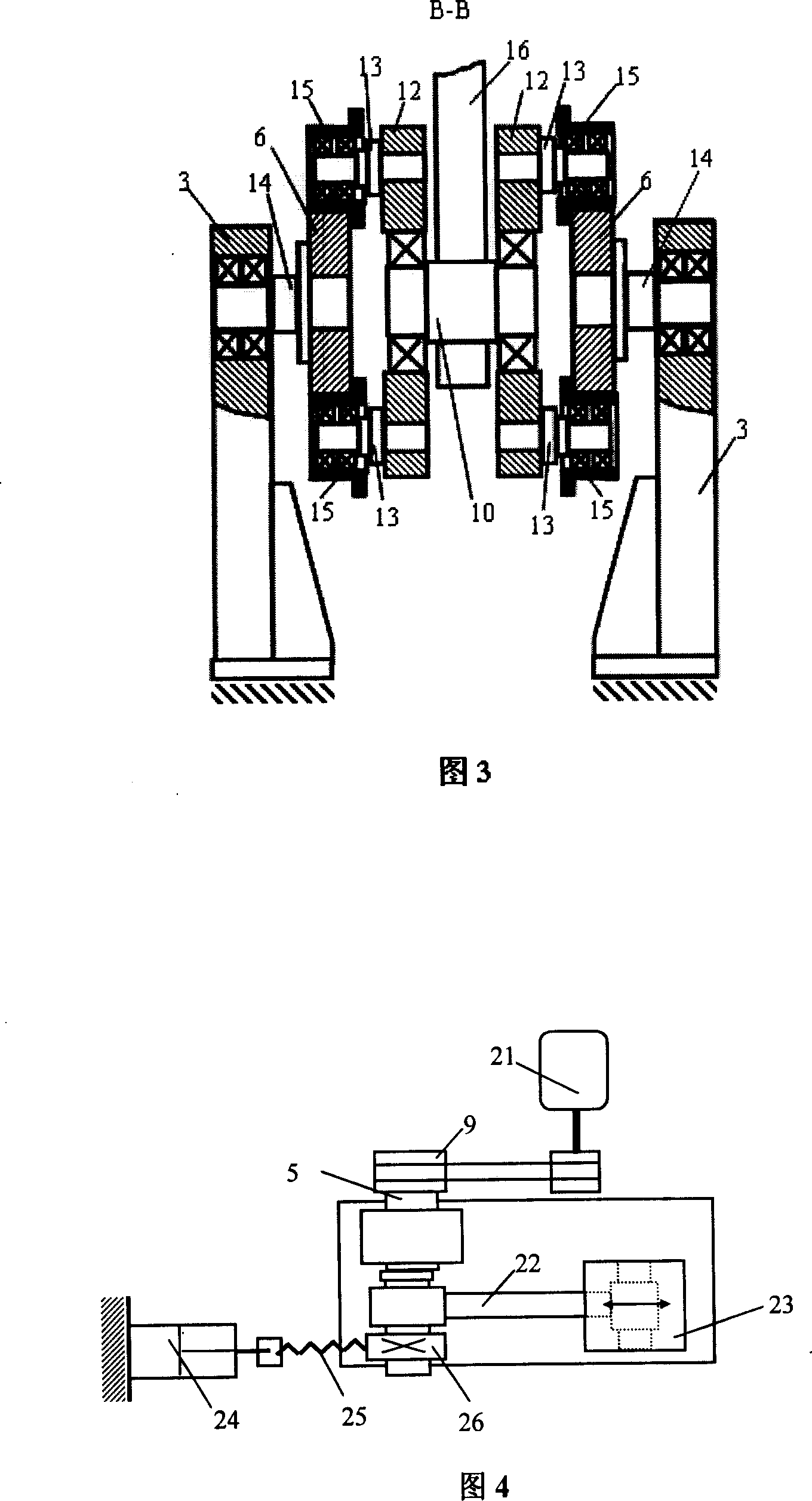
The main disadvantage of this limiting device is: 1. When the motor 21 stops, the position where the moving weldment stops is random, and the distance that the rack 25 pushes the limit gear 26 to rotate is different, that is, each time the driven weldment The distance from stopping the vibration to being pushed to the limit block is different, which will make the welding quality unstable; There will be a huge internal mechanical resistance between the gear 26 and the eccentric shaft 5, which will cause damage to the mechanical system of the equipment, and may even burn out the motor and frequency conversion equipment; 3. When the moving weldment is pushed to the limit block, it will cause a great impact , especially in large linear friction welding machines, this impact will not only reduce the quality of the weld, but also cause damage to the equipment after long-term use

Method used


Image

  • Vibrating mechanism
  • Vibrating mechanism

Examples


Embodiment Construction

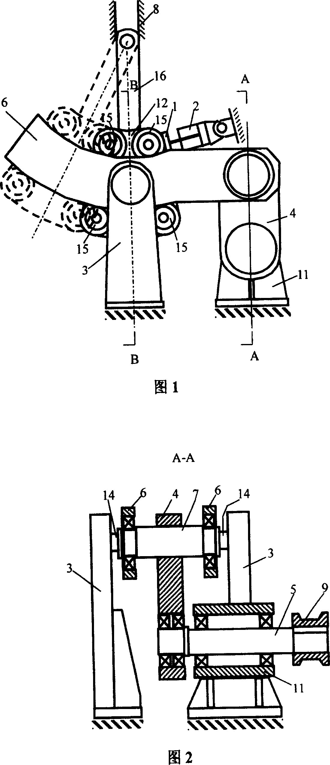
[0015] Referring to Figures 1 to 3, the eccentric shaft 5 is supported by the eccentric shaft support 11 through a pair of bearings, the pulley 9 is connected with the non-eccentric end of the eccentric shaft 5 through a flat key, and one end of the drive rod 4 is connected to the eccentric shaft 5 through a pair of bearings. The other end of the drive rod 4 is connected to the main rocker arms 6 on both sides through the main rocker arm connecting shaft 7, and the two ends of the main rocker arm connecting shaft 7 are respectively symmetrical to the main rocker arm 6 through a bearing. The two parts are connected. The pulley 9 is driven to rotate by the motor through the belt, and the eccentric shaft 5 drives the driving rod 4 to generate up and down reciprocating motion. The rotation center position of the main rocker arm 6 is respectively connected with two symmetrical parts of the main rocker arm support frame 3 through two main shafts 14 . Therefore, when the driving rod...


PUM


Abstract

The present invention discloses a vibration mechanism. Its characteristic is that a pair of main rockers which are connected by the main rockers' connect haulm is put on the main rockers' bracket and one side of driving haulm installs on the main rockers' connect haulm and the other one connects with the eccentricity side of the eccentricity axes which is supported by the eccentricity axes' abutment. The non-eccentricity side of the eccentricity axes fixes a strap wheel. The top of the handspike connects slide-rail by the gemel and the bottom connects separately slide blocks of two sides by the slide block connected axes. Then eight trolleys connects with the slide block by each trolley connected axes. The vibration mechanism can accommodate the swing, meet different materials, different shapes and dimension solders jointing technical demands and implement jointing accurate limited digit.

Description

technical field [0001] The invention relates to a vibrating mechanism, in particular to a vibrating mechanism for a linear friction welding machine. The amplitude of the vibration mechanism is adjustable and can be precisely limited. Background technique [0002] Referring to Fig. 4, the document "Vibration and Limiting Mechanism of Linear Friction Welding Machine, Chinese Patent, Patent No.: ZL200420041446.0" discloses a vibration and limiting mechanism of linear friction welding machine. The vibration mechanism is mainly composed of motor 21, pulley 9. It is composed of eccentric shaft 5, linkage rod 22, welding fixture base 23 and so on. One end of the linkage rod 22 is connected to the eccentric position of the eccentric shaft 5 through a bearing, and one end is connected to the welding fixture base 23 through a bearing. During welding, the motor 21 drives the eccentric shaft 5 to rotate through the belt pulley 9, and the linkage rod 22 produces a left-right reciprocat...

Claims


Application Information

Patent Timeline
Patent Type & Authority Patents(China)
IPC IPC(8): B23K20/12
Inventor 马铁军杨思乾
Owner NORTHWESTERN POLYTECHNICAL UNIV
Learn More