Separating and feeding device with head stick

A supply device and technology with a head, which is applied in the direction of transportation and packaging, conveyor objects, conveyors, etc., can solve the problems of increased resistance to take out the bar with the head, unable to take out the bar with the head, and lower suction retention rate, etc. Achieves the effect of improving suction retention rate, easy removal, and suppressing air consumption

Active Publication Date: 2008-02-13
NITTO SEIKO KO
View PDF3 Cites 2 Cited by
  • Summary
  • Abstract
  • Description
  • Claims
  • Application Information

AI Technical Summary

Problems solved by technology

[0003] In the existing separation and supply device, when taking out the headed rod from the support hole located at the highest position, if the air is continuously sucked from the suction hole connected to this, the removal resistance of the headed rod will increase, However, there are problems such as the inability to reliably remove the headed bar through a screwing machine or other removal machine.
In addition, if the suction of air from the suction hole at the highest position is stopped, the suction of air from the suction hole connected to the support hole near the lowest position will also stop, resulting in the air being sucked into the support hole near the lowest position, or The headed bar that is about to be inhaled falls off, and the suction retention rate of the headed bar in the support hole is significantly reduced, etc.

Method used


Image

  • Separating  and feeding device with head stick
  • Separating  and feeding device with head stick
  • Separating  and feeding device with head stick

Examples


Embodiment Construction

[0016] Hereinafter, the best mode for carrying out the present invention will be described with reference to the drawings.

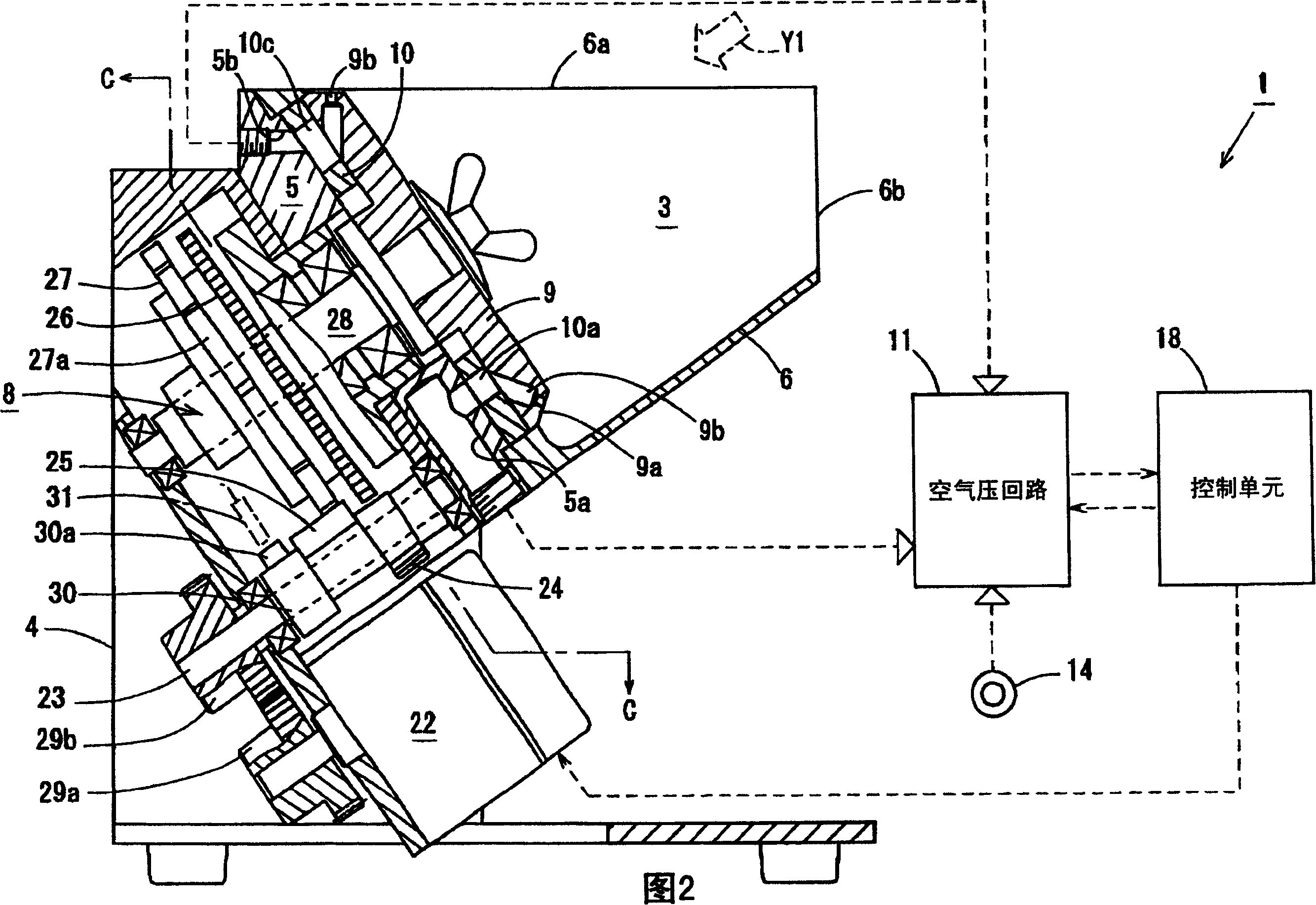
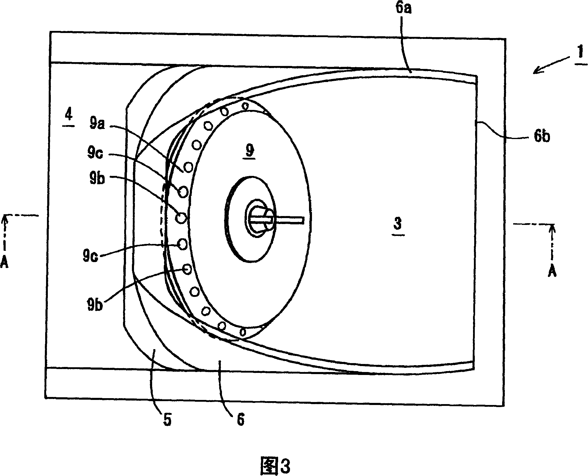
[0017] In Fig. 1 to Fig. 7, 1 is the separation and supply device (hereinafter referred to as the separation and supply device 1) of the bar with head, which is provided with a lot of small screws 2 (hereinafter referred to as abbreviation for short) as an example of the bar with head. is the hopper part 3 of the screw 2). This bucket part 3 is equipped with the base 5 attached to the base 4, and the cylindrical bucket part 6 attached to this base 5 inclined by predetermined angle. The upper opening end surface of the bucket 6 is formed as a horizontal surface 6a and a vertical surface 6b, thereby increasing the area of ​​the opening to facilitate screw insertion and improving visibility in the bucket 6 .

[0018] A disk-shaped separating plate 9 connected to an intermittent rotation drive mechanism 8 is disposed on a base 5 constituting the bottom of t...


PUM


Abstract

The invention provides a separating supply device with a head steel bar which can lead the head steel bar to be easily fetched out from a supporting hole on a fetching out position and improves the attracting maintaining rate in the supporting hole of the head steel bar. The invention is provided with a separating plate (9) which can rotate in hopper part (3) of the head steel bar that can store a plurality of small screws. On the outer circle part of the separating plate, a plurality of supporting holes (9b) that can be embedded with the head steel bar are collocated in equal distance. The supporting holes (9b) on the corresponding position of the head steel bar stored in the hopper part are communicated with an air absorption hole (5a) used for maintenance; besides, the supporting hole (9b) on a fixed fetching out position is communicated with an air absorption hole (5b) used for confirmation. Air is pumped in respectively from the absorption holes used for maintenance and confirmation. When maintaining the head steel bar in the supporting holes (9b) arranged on the fetching out position, the air absorption from the absorption hole used for confirmation and the air absorption from the absorption hole used for maintenance is continued.

Description

technical field [0001] The present invention relates to a separation and supply device for headed rods, which sucks and holds headed rods such as screws and rivets in support holes provided on the periphery of a separation plate, and supplies the headed rods to the established location. Background technique [0002] Conventionally, a device described in Patent Document 1 - Japanese Patent Application Laid-Open No. 2002-68461 is known as a device for separating and supplying a headed rod. This separate supply device has: a hopper part that can store many screws and other headed rods; it is installed at the bottom of the hopper part, and it can be horizontal to a predetermined angle and can rotate freely, and it is arranged at equal intervals on its outer circumference. A plurality of separation plates capable of fitting the support holes of the bar with a head, and air suction holes for sucking air from the support holes of the separation plates. The structure of the separa...

Claims


Application Information

Patent Timeline
Patent Type & Authority Patents(China)
IPC IPC(8): B65G29/00B65G47/14
Inventor 斋藤正幸新川诚西村尚树山本雅雄
Owner NITTO SEIKO KO
Why Eureka
Try Eureka