Camera provided with optical finder

A technology of optical viewfinder, camera, applied in the field of camera

Inactive Publication Date: 2008-02-27
OLYMPUS CORP
View PDF6 Cites 0 Cited by
  • Summary
  • Abstract
  • Description
  • Claims
  • Application Information

AI Technical Summary

Problems solved by technology

[0007] In addition, as a viewfinder function, there is a need to watch the electronic image of the shooting screen on a monitor. However, in the conventional method, the light beam is divided behind the pentaprism of the viewfinder and introduced into the imaging element unit, so the viewfinder part is enlarged. change

Method used


Image

  • Camera provided with optical finder
  • Camera provided with optical finder
  • Camera provided with optical finder

Examples


Embodiment Construction

[0016] Hereinafter, embodiments of the present invention will be described with reference to the drawings.

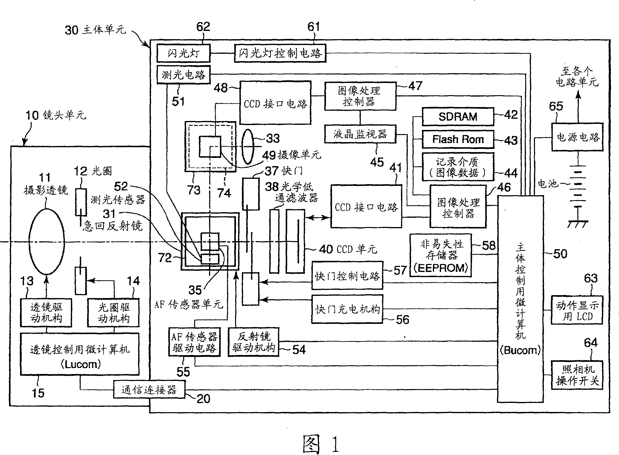
[0017] FIG. 1 is a block diagram showing a system configuration of a camera according to an embodiment of the present invention.

[0018] In FIG. 1 , the camera system is mainly composed of a lens unit 10 as an interchangeable lens and a main body unit 30 as a camera body, and a desired lens unit 10 is set to be detachable from the front of the main unit 30 .

[0019] The above-mentioned lens unit 10 can be freely attached and detached through an unillustrated lens mount provided on the front of the above-mentioned main body unit 30 . In addition, the lens unit 10 is composed of a photographic lens 11 , a diaphragm 12 , a lens driving mechanism 13 , a diaphragm driving mechanism 14 , and a microcomputer (hereinafter abbreviated as Lμcom) 15 for lens control.

[0020] The imaging lens 11 described above is driven in the optical axis direction by a DC motor (not shown) p...


PUM


Abstract

According to the present invention, light from a taking lens is reflected by a quick return mirror in a lateral direction of a body unit. Then, after passing through a screen, the light is reflected toward an upper side of the body unit by a second mirror except part of the light. The light reflected by the second mirror is reflected by a third mirror in a direction opposite to a direction in which the light is reflected by the quick return mirror, and is further reflected by a fourth mirror toward an eyepiece located on a back side of the body unit. Part of the light which passing though the screen is taken by an AF sensor unit provided in rear of the second mirror, and an image formation position of an optical image is detected.

Description

technical field [0001] The present invention relates to a camera having an optical viewfinder, and more particularly to the arrangement of an automatic focus detection unit, an exposure metering unit, and an imaging element unit for a viewfinder function in the camera. Background technique [0002] Conventionally, a single-lens reflex camera (hereinafter referred to as a single-lens reflex camera) using a Dach prism is generally known as a technology related to a TTL viewfinder, an automatic focus detection unit, an exposure metering unit, and a viewfinder function. A single-lens reflex camera using the Daher prism is composed of, for example, the following parts: a snap-back mirror driven to rotate up and down; a screen arranged above the snap-back mirror; a Daher prism arranged above the screen; eyepiece. [0003] In addition, in this form, the optical path is bent downward by the sub-mirror arranged behind the snap-back mirror, and an automatic focus detection mechanism ...

Claims


Application Information

Patent Timeline
Patent Type & Authority Patents(China)
IPC IPC(8): G02B7/28G03B13/02G03B7/099G03B19/12G02B17/08G03B7/0997G03B13/06H04N5/225H04N101/00
CPCG03B7/099
Inventor 川合澄夫鹫头洋一加藤孝二岩濑滋寺田洋志加藤茂
Owner OLYMPUS CORP
Why Eureka
Try Eureka